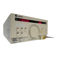
Tunable Semiconductor Laser TSL-710
6-3 Switching the Optical Power Control Mode 6-4
6-4 Setting the Trigger Output 6-5
6- 4 -1 Setting the Trigger Output 6-5
6- 4 - 2 Setting the Trigger Input 6-7
6- 4 - 3 Wavelength Logging 6-7
6-5 External Modulation 6-8
6-5-1 Low-frequency Modulation 6-8
6-5-2 High-frequency Modulation (Option) 6-10
6-6 Analog Signal Input 6-11
6-7 Power Monitor Signal Output 6-12
6-8 Wavelength Memory Function 6-13
6-8-1 Wavelength Readout 6-13
6-8-2 Wavelength Registration 6-14
6-9
Changing the Unit of the Wavelength
6-15
6-10
Changing the Unit of the Power
6-16
6-11 Internal Shutter 6-17
6-12 Displaying the Product Information 6-18
7. OperatIon By Communication 7-1
7-1 GPIB 7-1
7-1-1 Connection 7-1
7-1-2 GP-IB Function 7-2
7-1-3 Setting the Address, Delimiter, and Command set 7-3
7-2 RS-232C 7-4
7-2-1 Connection 7-4
7-2-2 Setting the Transmission Speed, and the Delimiter 7-5
7-2-3 Command 7-5
7-3 USB 7-5
7-3-1 Connection 7-5
7-3-2 Communication Conditions and System Requirements 7-6
7-3-3 Installing a USB Driver Software 7-7
7-3-4 Installing a VCP Driver Software 7-11
7-3-5 Command 7-16
7-4 Command Reference
7-16
7-4-1 Command set 1 (Complies with IEEE-488.2) 7-17
7-4-2 TSL-710 Specic Command set List (Command set 2) 7-47
8. Operating Principles 8-1