5.2
SEL-551 Relay Instruction Manual Date Code 20110408
Serial Port Communications and Commands
Port Connector and Communications Cables
Pinouts for EIA-232 and EIA-485 rear-panel serial communications port
options are as follows:
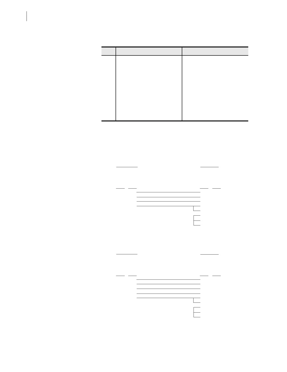
The following cable diagrams show several types of EIA-232 serial
communications cables. These and other cables are available from SEL.
Contact the factory for more information.
SEL-551 to Computer
Pin EIA-232 Option EIA-485 (4-wire) Option
1 N/C or +5 Vdc
a
a
Main board jumper JMP14 in the SEL-551 relay (see Section 2: Installation).
+TX
2 RXD –TX
3 TXD N/C
4 +IRIG-B +IRIG-B
5 GND SHIELD
6 –IRIG-B –IRIG-B
7RTS +RX
8 CTS –RX
9 GND SHIELD
SEL-551 Relay
9-Pin Male
"D" Subconnector
9-Pin Female
"D" Subconnector
2
3
5
8
3
2
5
8
7
1
4
6
RXD
TXD
GND
CTS
TXD
RXD
GND
CTS
RTS
DCD
DTR
DSR
Pin
Func.
Pin
Func.
Pin # Pin #
Cable SEL-C234A
*DTE Device
9-Pin Male
"D" Subconnector
25-Pin Female
"D" Subconnector
5
3
2
9
8
7
3
2
1
4
5
6
8
20
GND
TXD
RXD
GND
CTS
GND
RXD
TXD
GND
RTS
CTS
DSR
DCD
DTR
Pin
Func.
Pin
Func.
Pin # Pin #
Cable SEL-C227A
*DTE Device
*DTE = Data Terminal Equipment (Computer, Terminal, etc.)
SEL-551 Relay