3.39
Date Code 20110408 Instruction Manual SEL-551 Relay
Relay Elements and Logic
Output Contacts
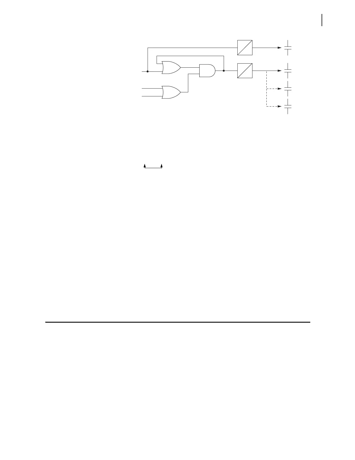
Figure 3.22 Dedicated Breaker Failure Scheme Created With SELOGIC
Variables/Timers
Note that the above SELOGIC control equation setting SV7 creates a seal-in
logic circuit (as shown in Figure 3.22) by virtue of SEL
OGIC control equation
setting SV7 being set equal to Relay Word bit SV7:
SV7 = (SV7 + IN1) * (50P1 + 50N1)
Optoisolated input IN1 functions as a breaker failure initiate input. Phase
instantaneous overcurrent element 50P1 and neutral ground instantaneous
overcurrent element 50N1 function as fault detectors.
Timer pickup setting SV6PU provides retrip delay, if desired (can be set to
zero). Timer dropout setting SV6DO holds the retrip output (output contact
OUT1) closed for extra time if needed after the breaker failure initiate signal
(IN1) goes away.
Timer pickup setting SV7PU provides breaker failure timing. Timer dropout
setting SV7DO holds the breaker failure trip output (output contact OUT2)
closed for extra time if needed after the breaker failure logic unlatches (fault
detectors 50P1 and 50N1 drop out).
Note that Figure 3.22 suggests the option of having output contacts OUT3 and
OUT4 operate as additional breaker failure trip outputs. This is done by making
the following SEL
OGIC control equation settings:
OUT3 = SV7T (breaker failure trip)
OUT4 = SV7T (breaker failure trip)
Output Contacts
SELOGIC control equation settings OUT1–OUT4 control Relay Word bits
OUT1–OUT4, respectively. Relay Word bits OUT1–OUT4 in turn control
output contacts OUT1 through OUT4, respectively. Dedicated alarm logic/
circuitry controls the ALARM output contact. See Figure 3.23 for the output
contacts available with the SEL-551 relay.
Factory Settings
Example
In the factory SELOGIC control equation settings, three output contacts are
used:
OUT1 = TRIP (overcurrent tripping/manual tripping; see Trip Logic on
page 3.17)
OUT2 = CLOSE (automatic reclosing/manual closing; see Close Logic on
page 3.20)
IN1
50P1
50N1
SV7 SV7T
SV6 SV6T
OUT1
(Retrip)
OUT2
(Breaker
Failure
Trip)
OUT3
OUT4
SV7PU
SV6PU
SV6D0
SV7D0