2.7
Date Code 20110408 Instruction Manual SEL-551 Relay
Installation
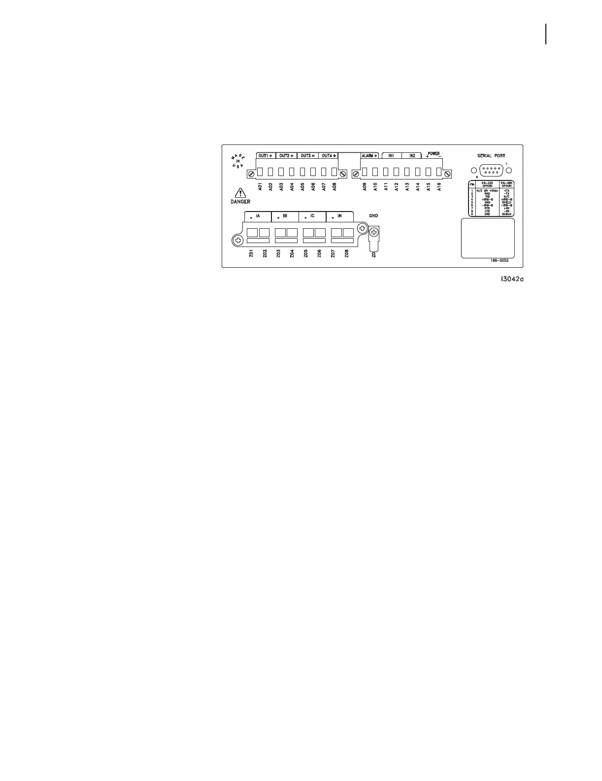
Rear-Panel Connections
Connectorized
To use the Connectorized version of the SEL-551, ask your SEL sales or
customer service representative for the appropriate Model Option Table and
order wiring harness kit WA05510WxXyA, where x designates wire size and y
designates wire length. You can find the Model Option Table on the SEL
website at http://www.selinc.com. Refer to Figure 2.8 to make all
Connectorized connections.
Figure 2.8 SEL-551 Rear Panel (Plug-In Connectors Option)
Connector terminals A01–A16 accept wire size AWG 24 to 12 (install wires
with a small slotted-tip screwdriver).
Output contacts OUT1–OUT4 and ALARM are polarity dependent (note the “+”
above terminals A02, A04, A06, A08, and A10).
As an example, consider the connection of terminals A01 and A02 (output
contact OUT1) in a circuit:
Terminal A02 (+) has to be at a higher voltage potential than terminal A01 in the
circuit.
With this option, output contacts OUT1–OUT4 and ALARM are also high-current
interrupting output contacts:
10 A for L/R = 40 ms at 125 Vdc
10 A for L/R = 20 ms at 250 Vdc
See High-Current Interrupting Output Contacts for more information.
Optoisolated inputs IN1 and IN2 are not polarity dependent.
Current input connector (terminals Z01–Z08):
➤ Contains current transformer shorting mechanisms
➤ Accepts wire size AWG 16 to 10 (special tool required to attach
wire to connector)
➤ Can be ordered prewired
Ground connection (terminal Z09): tab size 0.250 inch x 0.032 inch, screw size
#6-32.