F.2
SEL-551 Relay Instruction Manual Date Code 20110408
Setting Negative-Sequence Overcurrent Elements
Coordinating Negative-Sequence Overcurrent Elements
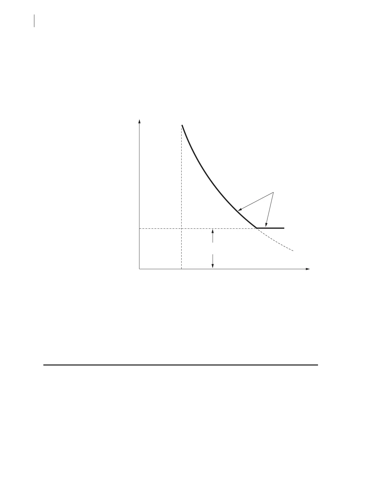
To avoid having negative-sequence time-overcurrent elements with such low
time-dial settings trip for this transient negative-sequence current condition,
make settings similar to the following:
SV6PU = 1.500 cycles (minimum response time; transient condition lasts
less than 1.5 cycles)
SV6 = 51Q1 (run pickup of negative-sequence time-overcurrent element
51Q1T through SEL
OGIC Variable timer SV6)
TR = ..+51Q1T*SV6T+.. (trip conditions; SV6T is the output of the
SEL
OGIC Variable timer SV6)
Figure F.1 Minimum Response Time Added to a
Negative-Sequence Time-Overcurrent Element
Continue reading in Coordinating Negative-Sequence Overcurrent Elements
on page F.2 for guidelines on coordinating negative-sequence time-
overcurrent elements and a following coordination example.
Coordinating Negative-Sequence Overcurrent
Elements
The following coordination guidelines and example assume that the negative-
sequence overcurrent elements operate on 3I
2
magnitude negative-sequence
current and that the power system is radial. The negative-sequence overcurrent
elements in the SEL-551 Relay operate on 3I
2
magnitude negative-sequence
current.
The coordination example is a generic example that can be used with any relay
containing negative-sequence overcurrent elements that operate on 3I
2
magnitude negative-sequence current. The SEL-551 can be inserted as the
51Q1T*SV6T
I (3I
2
)51Q1
SV6PU
t