8.12
SEL-551 Relay Instruction Manual Date Code 20110408
Testing and Troubleshooting
Acceptance Testing
b. Subtract the time from the assertion of the pickup (i.e.,
51P1) to the assertion of the time-delayed element (i.e.,
51P1T).
SER C clears the Sequential Event Records.
Step 5. Purpose:
Repeat the test for each inverse-time overcurrent element.
Method:
a. Repeat Step 1–Step 4 for each time element listed in
Table 8.2 for each phase.
b. Remember to set the SER for the appropriate elements
and apply current to the appropriate phase.
The neutral ground overcurrent elements operate based
on current applied to the separate IN input.
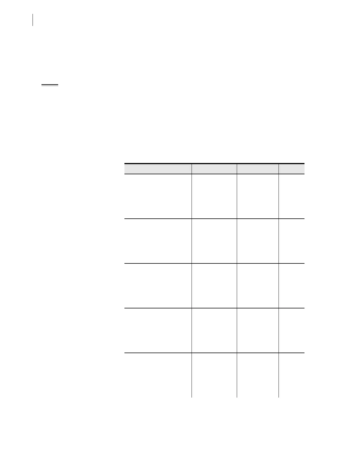
Table 8.2 Inverse-Time Overcurrent Elements and Corresponding Settings/
Relay Word Bits/TAR Commands (Sheet 1 of 2)
Element/Settings Setting Names Relay Word Bits TA R
Phase Level 1 51P1 1
Pickup 51P1P (picked up)
Curve 51P1C
Time-Dial 51P1TD 51P1T 1
Electromechanical Reset 51P1RS (timed out)
Phase Level 2 51P2 1
Pickup 51P2P
Curve 51P2C
Time-Dial 51P2TD 51P2T 1
Electromechanical Reset 51P2RS (timed out)
Neutral Ground 51N1 1
Pickup 51N1P (picked up)
Curve 51N1C
Time-Dial 51N1TD 51N1T 1
Electromechanical Reset 51N1RS (timed out)
Residual Ground 51G1 1
Pickup 51G1P (picked up)
Curve 51G1C
Time-Dial 51G1TD 51G1T 1
Electromechanical Reset 51G1RS (timed out)
Negative-Sequence Level 1 51Q1 2
Pickup 51Q1P (picked up)
Curve 51Q1C
Time-Dial 51Q1TD 51Q1T 2
Electromechanical Reset 51Q1RS (timed out)
NOTE: If the electromechanical
induction-disk reset emulation is
enabled (i.e., 51P1RS = Y), the element
under test may take some time to
reset fully. If the element is not fully
reset when you run a second test, the
time to trip will be lower than
expected. Usually this setting is set
51P1RS = N.