2.6
SEL-551 Relay Instruction Manual Date Code 20110408
Installation
Rear-Panel Connections
and many industry applications have proven the performance of these
connectors. In addition, we have tested these connectors thoroughly to ensure
that they conform to our standards for protective relay applications.
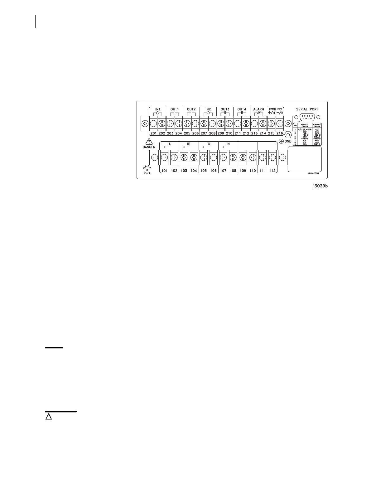
Terminal Block
Make terminal block connections with size #6-32 screws using a Phillips
®
or
slotted screwdriver. You may request locking screws from the factory. Refer to
Figure 2.7 to make all terminal block connections.
Figure 2.7 SEL-551 Rear Panel (Conventional Terminal Blocks Option)
The output contacts in Figure 2.7 (OUT1–OUT4 and ALARM) are not polarity
dependent.
The optoisolated inputs in Figure 2.7 (IN1–IN2) are not polarity dependent.
All screws are size #6-32.
Screw Terminal Connections
All screw/washer styles on SEL relays are recognized by UL for field wiring
using terminals or bare wire. However, as stated below, SEL strongly
recommends the use of ring or fork terminals.
Two types of screw terminal are provided on the SEL relays, one with a
washer (Phillips screw head - standard) and one without (slotted screw head,
optional). SEL recommends using ring or fork terminals with both types of
screw terminals fitted to the relays. There are two main reasons for this
recommendation;
Step 1. Stray strands and inconsistent wire stripping may compromise
hi-pot clearances and give rise to the potential for shorting the
adjacent terminals.
Step 2. Wire/terminal secureness with ring terminals has been tested at
SEL to 20 lb minimum. Bare wire has not been tested at SEL.
Both the terminal block manufacturer and UL requirements have qualified the
standard terminal blocks for use with bare stranded wire, however, SEL’s
qualification requirements are more stringent as required by the utility and
industrial applications of protective relays.
The SEL terminal retention and hi-pot test voltage requirements are both
twice that required by the UL standard.
All SEL qualification testing of terminal blocks and relays is performed with
ring or fork terminals.
NOTE: #6 ring and fork terminals
will accommodate wire sizes from 22
awg to 10 awg.
There is no limit to the number of
terminals that can be clamped under
one screw, however there is a
maximum total thickness of .120" (3
mm). Ring terminals typically range in
thickness .030" to .060".
A too-long screw will damage the
inside part of the terminal. This is true
for both styles of terminal block, but
especially for the I/O connections.