3.43
Date Code 20110408 Instruction Manual SEL-551 Relay
Relay Elements and Logic
Demand Ammetering
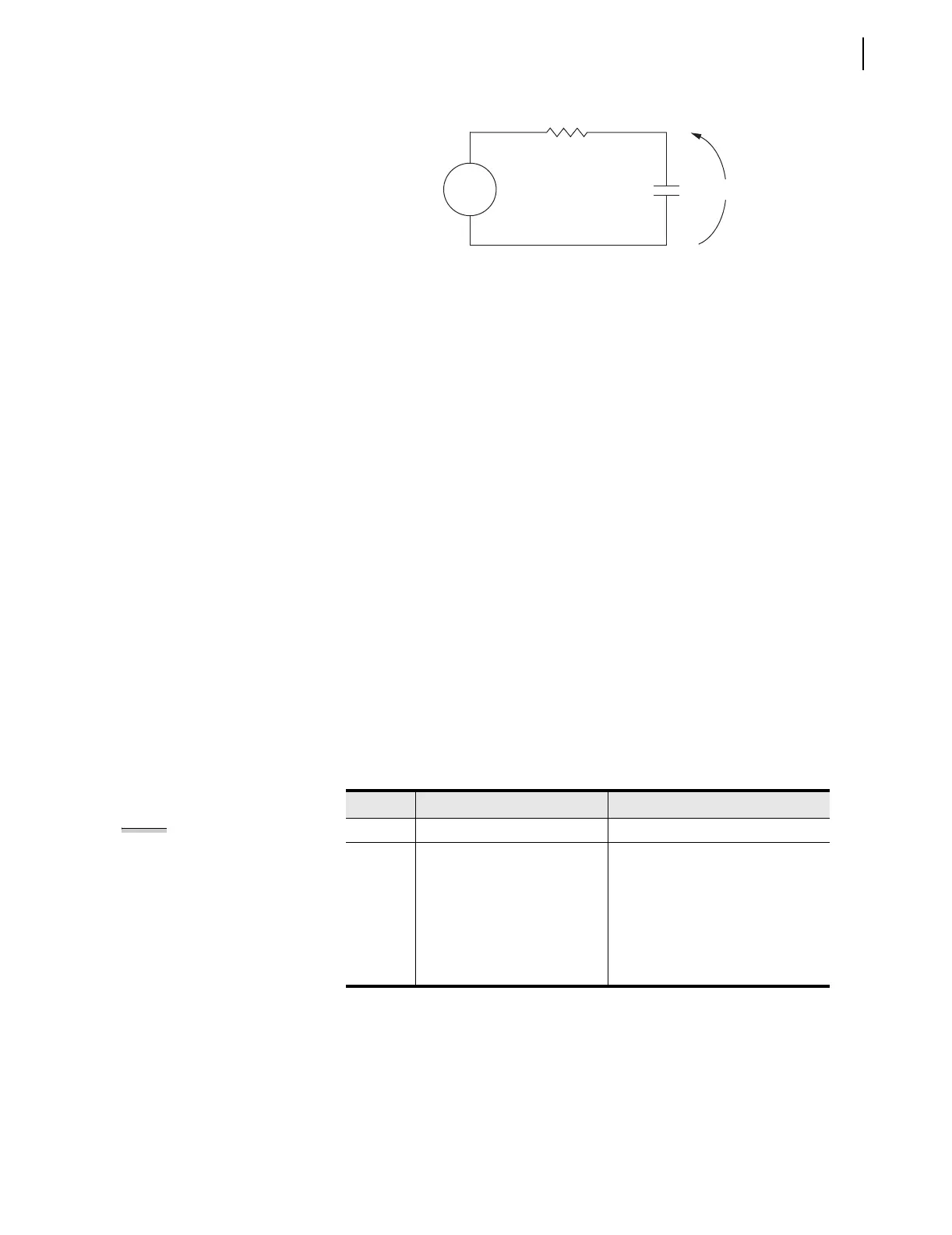
Figure 3.25 Voltage V
S
Applied to Series RC Circuit
In the analogy:
Voltage V
S
in Figure 3.25 corresponds to the step current input
Figure 3.24 (top).
Voltage V
C
across the capacitor in Figure 3.25 corresponds to the
response of the thermal demand ammeter in Figure 3.24 (bottom).
If voltage V
S
in Figure 3.25 has been at zero (V
S
= 0.0 per unit) for some
time, voltage V
C
across the capacitor in Figure 3.25 is also at zero (V
C
= 0.0
per unit). If voltage V
S
is suddenly stepped up to some constant value (V
S
=
1.0 per unit), voltage V
C
across the capacitor starts to rise toward the 1.0 per
unit value. This voltage rise across the capacitor is analogous to the response
of the thermal demand ammeter in Figure 3.24 (bottom) to the step current
input (top).
In general, as voltage V
C
across the capacitor in Figure 3.25 cannot change
instantaneously, the thermal demand ammeter response is not immediate
either for the increasing or decreasing applied instantaneous current. The
thermal demand ammeter response time is based on the demand ammeter time
constant setting DMTC (see Table 3.7). Note in Figure 3.24 the thermal
demand ammeter response (bottom) is at 90 percent (0.9 per unit) of full
applied value (1.0 per unit) after a time period equal to setting DMTC =
15 minutes, referenced to when the step current input is first applied.
The SEL-551 updates thermal demand values approximately every two
seconds.
Demand Ammeter
Settings
The demand current pickup settings in Ta ble 3.7 are applied to demand current
meter outputs as shown in Figure 3.26. For example, when residual ground
demand current I
G(DEM)
goes above corresponding demand pickup GDEMP,
Relay Word bit GDEM asserts to logical 1. Use these demand current logic
outputs (PDEM, NDEM, GDEM, and QDEM) to alarm for high loading or
unbalance conditions. Use in other schemes such as the following example.
Table 3.7 Demand Ammeter Settings and Settings Range
Setting Definition Range
DMTC Demand meter time constant 5, 10, 15, 30, or 60 minutes
PDEMP Phase demand current pickup
OFF, 0.50–16.00 A {5 A nominal},
0.10–3.20 A {1 A nominal},
in 0.01 A steps
NDEMP Neutral ground
demand current pickup
GDEMP Residual ground
demand current pickup
QDEMP Negative-sequence
demand current pickup
NOTE: Changing setting DMTC
resets the demand ammeter values to
zero. Demand current pickup settings
PDEMP, NDEMP, GDEMP, and QDEMP
can be changed without affecting the
demand ammeters.