3.10
SEL-551 Relay Instruction Manual Date Code 20110408
Relay Elements and Logic
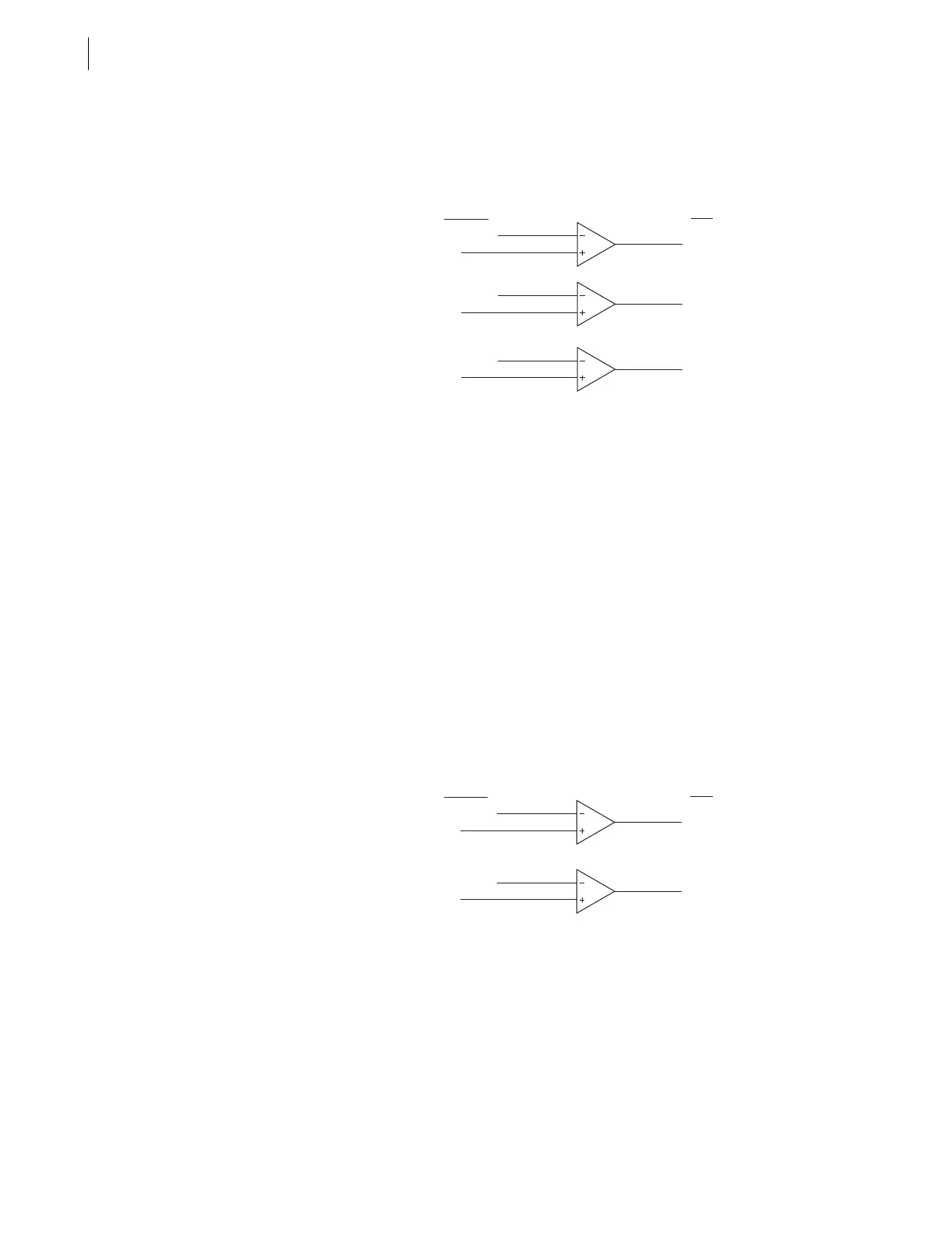
Instantaneous Overcurrent Elements
into 50B logic is the maximum phase B current output of cosine filter
algorithm, and the I
C
input into 50C logic is the maximum phase C current
output of cosine filter algorithm.
Figure 3.5 Single-Phase Instantaneous Overcurrent Elements 50A, 50B,
and 50C
Example 50A element operation:
I
A
> pickup setting 50ABCP, then Relay Word bit 50A = logical 1
I
A
≤ pickup setting 50ABCP, then Relay Word bit 50A = logical 0
If pickup setting 50ABCP is set to 50ABCP = OFF, then element 50A is
disabled. Relay Word bit 50A equals logical 0 at all times.
The other two phase instantaneous overcurrent elements (50B and 50C)
operate similarly.
Neutral Ground
Instantaneous
Overcurrent Elements
Two neutral ground instantaneous overcurrent elements (50N1 and 50N2) are
available (see Figure 3.6). Their pickup settings (50N1 and 50N2,
respectively) are compared to the magnitude of the neutral ground current
(I
N
). This current is from separate neutral current input channel IN (see
Figure 1.2).
Figure 3.6 Neutral Ground Instantaneous Overcurrent Elements 50N1 and
50N2
Example 50N1 element operation:
I
N
> pickup setting 50N1P, then Relay Word bit 50N1 = logical 1
I
N
≤ pickup setting 50N1P, then Relay Word bit 50N1 = logical 0
If pickup setting 50N1P is set to 50N1P = OFF, then element 50N1 is
disabled. Relay Word bit 50N1 equals logical 0 at all times.
The second neutral ground instantaneous overcurrent element (50N2) operates
similarly.
Relay
Word
Bits
Settings/
Currents
50ABCP
I
A
50ABCP
50ABCP
I
B
I
C
50A
50B
50C
Relay
Word
Bits
Settings/
Currents
50N1P
I
N
50N2P
I
N
50N1
50N2