1.3
Date Code 20110408 Instruction Manual SEL-551 Relay
Introduction and Specifications
Hardware Overview
Hardware Overview
➤ Rear-panel: conventional terminal blocks or plug-in connectors
(see Figure 2.7 and Figure 2.8)
➤ High-current interrupting output contacts: 10 A for L/R =
40 ms at 125 Vdc (included in the rear-panel plug-in
connectors option only—see Figure 2.8)
➤ Rear-panel serial communications port: EIA-232 or EIA-485
(4-wire)-either option includes a demodulated IRIG-B time-
code input (see Figure 2.7 and Figure 2.8)
q See Figure 2.8; w see Figure 2.10; e see Figure 2.11; r see Figure 2.12; t see Figure 2.9, Figure 2.13, and Figure 2.14.
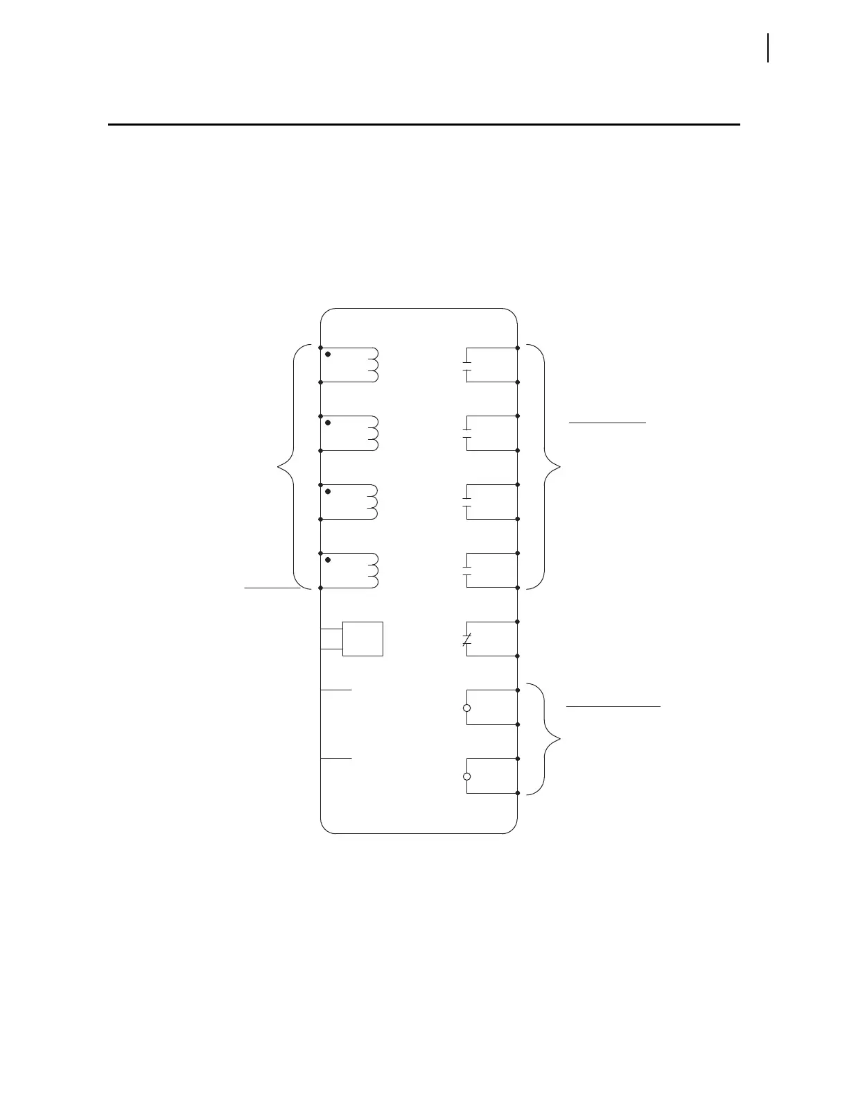
Figure 1.2 SEL-551 Inputs, Outputs, and Communications Port
time-code input)
(includes
demodulated
IRIG-B
–
+
Supply
Power
– Ground residual circuit
current transformer
– Tertiary winding
current transformer
– Separate neutral
current transformer
– Core-balance
channel IN to:
neutral current input
Connect the separate
connectors option only)
in the rear-panel plug-in
connector available (included
Unique current input channel
Serial Port
EIA-485
or
EIA-232
GND
– Breaker status
– Overcurrent element
torque-control
to assert optoisolated inputs.
Apply nominal dc control voltage
Example Functions:
Optoisolated Inputs
Programmable
plug-in connectors option.
output contacts in the rear-panel
with the high-current interrupting
There is a polarity dependence
– Breaker failure
– Close
– Trip
Example Functions:
Output Contacts
Programmable
IN2
IN1
ALARM
OUT4
IN
OUT3
OUT2
OUT1
IC
IB
IA
SEL-551 RELAY
q
w
e
r
t
q