3.40
SEL-551 Relay Instruction Manual Date Code 20110408
Relay Elements and Logic
Output Contacts
OUT3 = SV5T (breaker failure trip; see SELOGIC Control Equation
Variables/Timers on page 3.38)
OUT4 = 0 (output contact OUT4 not used-set to logical 0)
Figure 1.2 shows the factory configuration of the output contacts for the SEL-
551 relay.
Operation of Output
Contacts for
Different Output
Contact Types
q PULSE command is also available via the front panel ({CNTRL} pushbutton, output
contact testing
option). Execution of the PULSE command results in a logical 1
input into the above logic.
w Main board jumper JMP13 allows output contact OUT4 to operate as: regular
output contact OUT4 (JMP13 in position YOUT2), an extra Alarm output contact
(JMP13 in position ALARM). See Figure 2.16 and Tabl e 2.2 for more information.
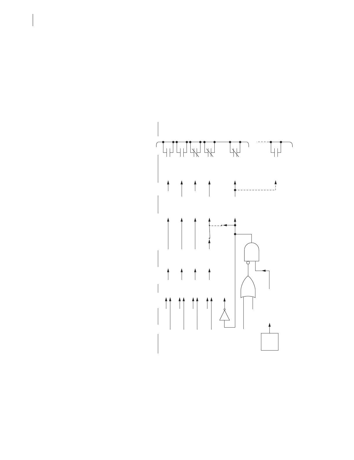
Figure 3.23 Logic Flow for Example SEL-551 Output Contact Operation
OpenOUT1 (a)De-energizedLogical 0OUT1
OUT1
PULSE OUT1
Output
Contact
Coil States
SEL
OGIC
Control
Equations
Settings
Relay
Word
Bits
Example
Relay
Word Bits
States
Serial Port
Commands
(see q)
Output Contacts
(and example
contact types)
Output
Contact
Terminal
States
Closed
Closed
OUT2 (a)EnergizedLogical 1OUT2
OUT2
PULSE OUT2
OUT3 (b)De-energizedLogical 0OUT3
OUT3
PULSE OUT3
OpenOUT4 (b)Energized
Energized
or
De-energized
Logical 1 (relay OK)
or
Logical 0 (relay failed)
Logical 1
(YOUT2)
(ALARM)
JMP13
(see w)
Alarm
Logic/
Circuitry
OUT4
OUT4
PULSE OUT4
PULSE ALARM
Relay Enters Access Level 2
Open (relay OK)
or
Closed (relay failed,
de-energized, etc.)
ALARM (b)
ALARM
Closed (relay OK)
or
Open (relay failed,
de-energized, etc.)
ALARM (a)