8.17
Date Code 20110408 Instruction Manual SEL-551 Relay
Testing and Troubleshooting
Relay Troubleshooting
Relay Troubleshooting
Inspection Procedure
Complete the following procedure before disturbing the relay. After you finish
the inspection, proceed to the Troubleshooting Procedure.
Step 1. Measure and record the power supply voltage at the power
input terminals.
Step 2. Check to see that the power is on. Do not turn the relay off.
Step 3. Measure and record the voltage at all control inputs.
Step 4. Measure and record the state of all output relays.
Troubleshooting
Procedure
RAM Failure Yes Latched Performs a read/write test
on system RAM every 60 seconds.
ROM Failure checksum Yes Latched Performs a checksum test on the relay
program memory every 0.2 seconds.
CR_RAM Failure checksum Yes Latched Performs a checksum test
on the active copy of the
relay settings every 0.2 seconds.
EEPROM Failure checksum Yes Latched Performs a checksum test
on the nonvolatile copy of the
relay settings every 0.2 seconds.
The following self-tests are performed by dedicated circuitry in the microprocessor and the SEL-551 main board.
Failures in these tests shut down the microprocessor and are not shown in the STATUS report.
Microprocessor
Crystal
Failure Yes Latched The relay monitors the microprocessor
crystal. If the crystal fails, the relay dis-
plays
CLOCK STOPPED on the LCD
display. The test runs continuously.
Microprocessor Failure Yes Latched The microprocessor examines each pro-
gram instruction, memory access, and
interrupt. The relay displays
VECTOR nn
on the LCD upon detection of an invalid
instruction, memory access, or spurious
interrupt. The test runs continuously.
+5V PS
Under/Over
Voltage
Failure +4.65 V
+5.95 V
Yes Latched A circuit on the SEL-551 main board
monitors the +5 V power supply. Upon
detection of a failure, the circuit
forces the microprocessor to reset.
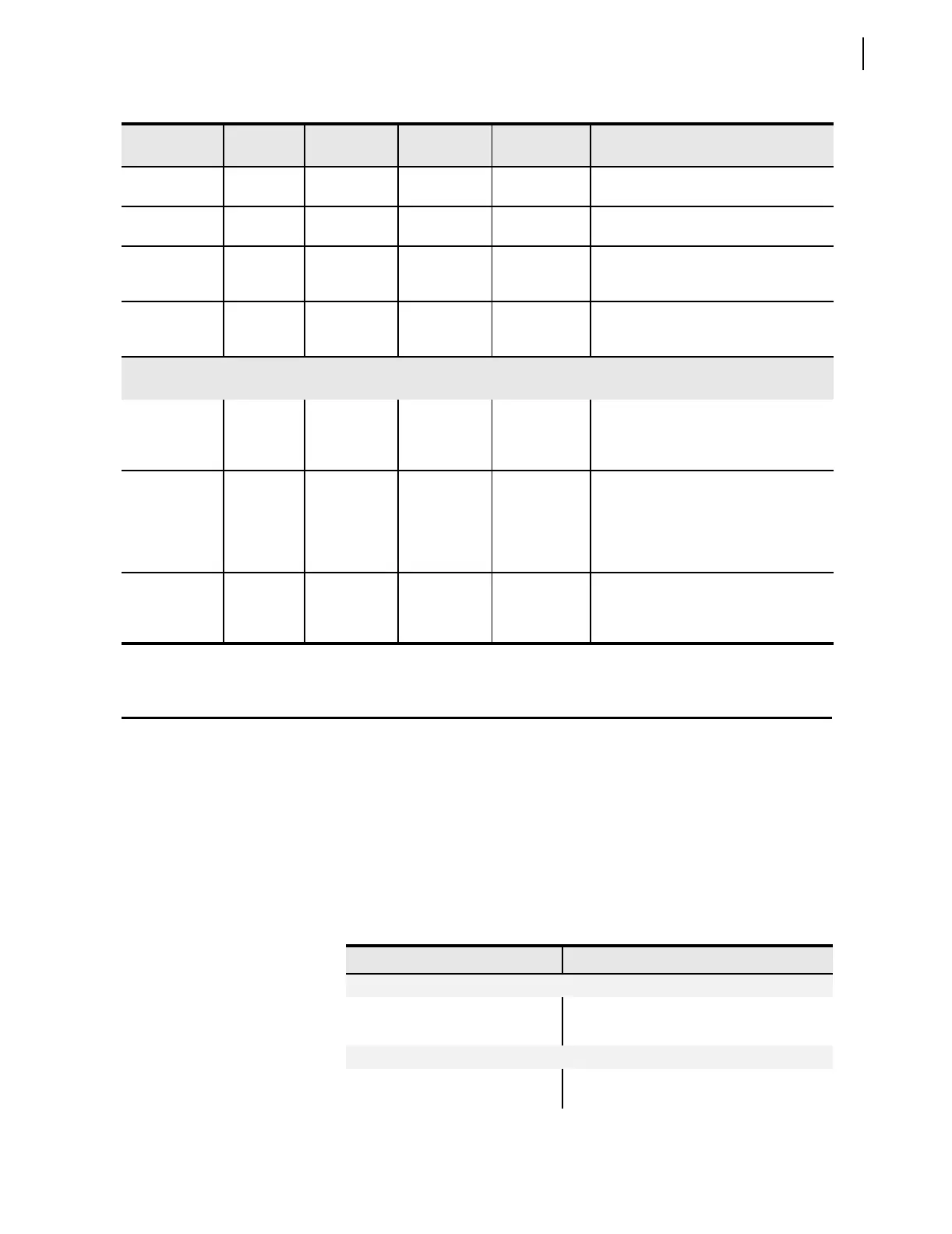
Table 8.3 Relay Self Tests (Sheet 2 of 2)
Self-Test Condition Limits
Protection
Disabled
ALARM Description
Table 8.4 Troubleshooting Procedures (Sheet 1 of 2)
Symptom/Possible Cause Diagnosis/Solution
All Front-Panel LEDs Dark
Input power not present or fuse is blown.
Self-test failure.
Cannot See Characters on Relay LCD Screen
Relay is de-energized. Check to see if the ALARM output contact is
closed.