8.2
SEL-551 Relay Instruction Manual Date Code 20110408
Testing and Troubleshooting
Testing Methods and Tools
For more information on these features and commands, see Section 5: Serial
Port Communications and Commands.
Low-Level Test
Interface
The SEL-551 has a low-level test interface between the calibrated input
module and the separately-calibrated processing module. You can test the
relay in either of two ways:
➤ conventionally, by applying ac current signals to the relay
inputs
➤ by applying low magnitude ac voltage signals to the low-level
test interface
Access the test interface by removing the relay front panel.
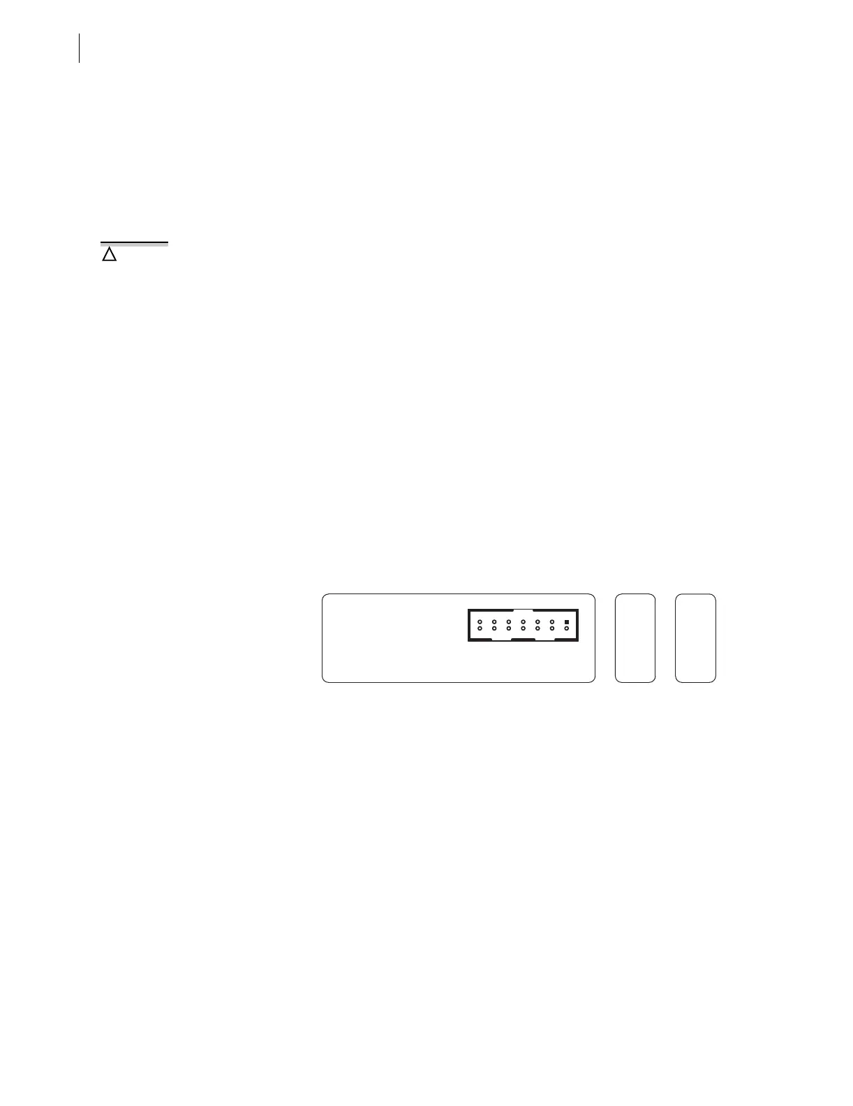
Figure 8.1 shows the low-level interface connections. Remove the ribbon
cable between the two modules to access the outputs of the input module and
the inputs to the processing module (relay main board).
You can test the relay processing module, using signals from the SEL RTS
Low-Level Relay Test System. Never apply voltage signals greater than 9 V
peak-to-peak to the low-level test interface. Figure 8.1 shows the signal
scaling factors.
You can test the input module two different ways:
1. Measure the outputs from the input module with an accurate
voltmeter, and compare the readings to accurate instruments in
the relay input circuits, or
2. Replace the ribbon cable, press the front-panel {METER} button,
and compare the relay readings to other accurate instruments in
the relay input circuits.
Figure 8.1 Low-Level Test Interface
Test Methods
Test the pickup and dropout of relay elements, using one of three methods:
➤ front-panel target LCD/LED indication
➤ output contact operation
➤ the Sequential Event Recorder (SER)
Target LED Illumination
Step 1. During testing, use target LED illumination to determine relay
element status.
Step 2. Using the TAR command, set the front-panel targets to display
the element under test.
The relay contains devices sensitive
to Electrostatic Discharge (ESD).
When working on the relay with the
front panel removed, work surfaces
and personnel must be properly
grounded or equipment damage may
result.
!
CAUTION
INPUT MODULE OUTPUT (J7) : 71.43 mV AT NOMINAL CURRENT (1 A OR 5 A)
SEL-551 157-0055
PROCESSING MODULE INPUT (J9) : 6.2 V p-p MAXIMUM
LOW-LEVEL TEST INTERFACE
PATENTS PENDING
FOR TESTING
REMOVE RIBBON CABLE
GNDGND GND GNDGND+10V GND
-10V N/C N/C IN IC IAIB
INPUT
MODULE
PROCESSING
MODULE