G.4
SEL-551 Relay Instruction Manual Date Code 20110408
Modbus RTU Communications Protocol
Modbus RTU Communications Protocol
To build the response, the relay calculates the number of bytes required to
contain the number of bits requested. If the number of bits requested is not
evenly divisible by 8, the relay adds one more byte to maintain the balance of
bits, padded by zeroes to make an even byte.
Input numbers are defined below:
Input addresses start at 0000 (i.e., input 1 is located at Input Address 0000).
The relay responses to errors in the query are shown below:
03h Read Holding
Register Command
Use function code 03h to read directly from the Modbus Register map shown
in Tabl e G.18. You may read a maximum of 125 registers at once with this
function code. Most masters use 4X references with this function code. If you
are accustomed to 4X references with this function code, for 5 digit
addressing, add 40001 to the standard database address.
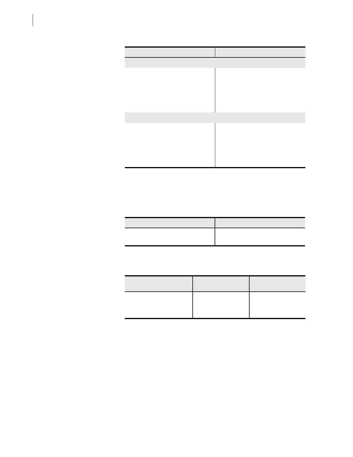
Table G.5 02h Read Input Status Command
Bytes Field
Requests from the master must have the following format:
1 byte Slave Address
1 byte Function Code (02h)
2 bytes Address of the First Bit
2 bytes Number of Bits to Read
2 bytes CRC-16
A successful response from the slave will have the following format:
1 byte Slave Address
1 byte Function Code (02h)
1 byte Number of Bytes of Data (n)
n bytes Data
2 bytes CRC-16
Input Numbers Description
1 Input 1
2 Input 2
Error Error Code Returned
Communication
Counter Increments
Invalid bit to read Illegal Data Address (02h) Invalid Address
Invalid number of bits to read Illegal Data Value (03h) Illegal Register
Format error Illegal Data Value (03h) Bad Packet Format