3.47
Date Code 20110408 Instruction Manual SEL-551 Relay
Relay Elements and Logic
Front-Panel Target LEDs
Front-Panel Target LEDs
Refer to Figure 2.5 for the arrangement of the target LEDs on the front panel
of the SEL-551 relay.
Further Target LED
Details
A, B, and C Target LEDs
The following overcurrent elements are used for phase targeting: 51P1,
51P1T, 51P2, 51P2T, 51Q1, 51Q1T, 51Q2, 51Q2T, 50P1, 50P2, 50P3, 50P4,
50P5, 50P6, 50Q1, 50Q2, 50A, 50B, 50C.
NOTE: Using elements that are not
targeting elements (SV5T–SV14T, for
example) in the TR equation may
produce unexpected results.
The A target LED illuminates if any phase targeting element is asserted after
the rising edge of TRIP, the asserted element is in the TR equation, and the
phase A current (current input IA) is above the overcurrent element pickup.
The A target LED also illuminates if a negative-sequence overcurrent element
is asserted, the asserted element is in the TR equation, and phase A is involved
in the fault.
The fault must be present for at least 1.5 cycles after the relay trips for reliable
targeting.
The logic for the B target LED and C target LED is similar.
N Target LED
The following overcurrent elements are used for ground targeting: 51N1,
51N1T, 51G1, 51G1T, 50N1, 50N2, 50G1, 50G2.
The N target LED illuminates if any ground targeting element is asserted after
the rising edge of TRIP and the asserted element is in the TR equation.
The fault must be present for at least 1.5 cycles after the relay trips for reliable
targeting.
INST Target LED
The INST target LED illuminates if Relay Word bit TRIP asserts less than three
cycles after a phase or ground targeting element asserts. Only the targeting
elements included in the TR equation are considered.
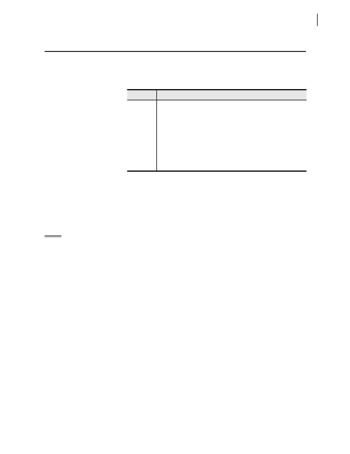
Table 3.8 SEL-551 Front-Panel Target LED Definitions
LED Definition
EN Relay Enabled—see subsection Relay Self-Tests on page 8.16
INST Instantaneous trip—see further details following
A Phase A involved in the fault—see further details following
B Phase B involved in the fault—see further details following
C Phase C involved in the fault—see further details following
N Ground involved in the fault—see further details following
RS Reclosing relay in the Reset State (follows Relay Word bit 79RS)
LO Reclosing relay in the Lockout State (follows Relay Word bit 79LO)