3.38
SEL-551 Relay Instruction Manual Date Code 20110408
Relay Elements and Logic
SEL
OGIC Control Equation Variables/Timers
SELOGIC Control Equation Variables/Timers
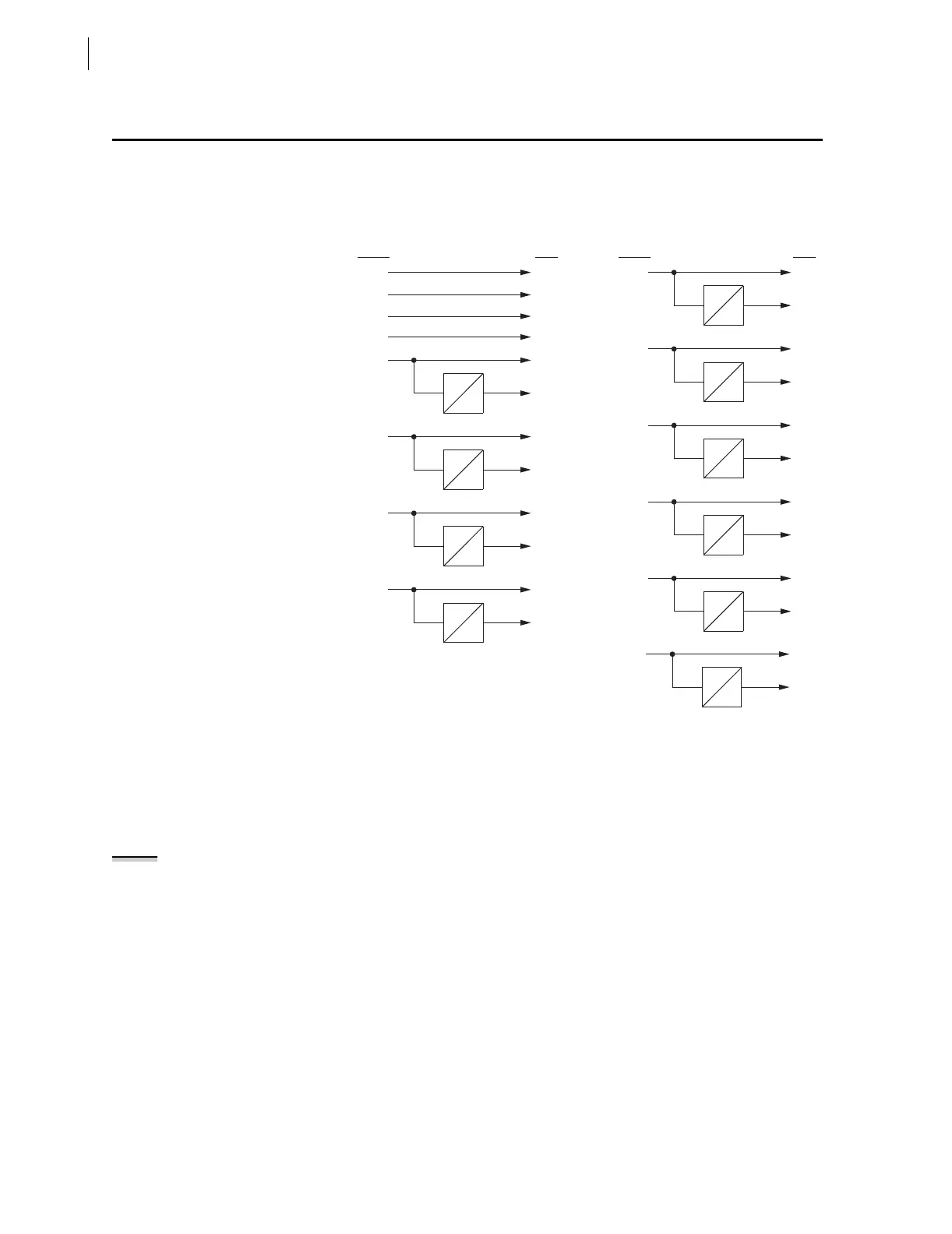
Fourteen SELOGIC Variables (SV1–SV14) are available. Ten of these
SEL
OGIC Variables have timer outputs, (SV5T–SV14T) (see Figure 3.21).
Figure 3.21 SELOGIC Control Equation Variables/Timers
Factory Settings
Example
In the factory SELOGIC control equation settings, a SELOGIC Var iable Timer
is used for a simple breaker failure scheme:
SV5 = TRIP
The TRIP Relay Word bit is run through a timer for breaker failure timing.
Timer pickup setting SV5PU is set to the breaker failure time (SV5PU = 12
cycles). Timer dropout setting SV5DO is set for a two cycle dropout (SV5DO
= 2 cycles). The output of the timer (Relay Word bit SV5T) operates output
contact OUT3 (SEL-551 factory setting only).
OUT3 = SV5T
Additional Settings
Example
Another application idea is dedicated breaker failure protection (see
Figure 3.22):
SV6 = IN1 (breaker failure initiate)
SV7 = (SV7 + IN1) * (50P1 + 50N1)
OUT1 = SV6T (retrip)
OUT2 = SV7T (breaker failure trip)
SV5T
SV5
SV4
SV3
SV2
SV1
SV5
SV4
SV3
SV2
SV1
SV5PU
SV5D0
SV6
SV6T
SV6
SV6PU
SV6D0
SV7
SV7T
SV7
SV7PU
SV7D0
SV8
SV8T
SV8
SV8PU
SV8D0
SV14
SV14T
SV14
SV14PU
SV14D0
SV9T
SV9 SV9
SV9PU
SV9D0
SV10
SV10T
SV10
SV10PU
SV10D0
SV11
SV11T
SV11
SV11PU
SV11D0
SV12
SV12T
SV12
SV12PU
SV12D0
SV13
SV13T
SV13
SV13PU
SV13D0
Relay
Word
Bits
Relay
Word
Bits
SELOGIC Variable/
Timer Input
Settings
SELOGIC Variable/
Timer Input
Settings
NOTE: The following SELOGIC
Variable Timer examples make use of
output contacts. Output Contacts on
page 3.39 shows what output
contacts are available in the SEL-551
relay
.