B.3
Date Code 20110408 Instruction Manual SEL-551 Relay
Firmware Upgrade Instructions
EPROM Firmware Upgrades
Step 12. With a slight downward pressure, rotate the extraction tool
away from the EPROM socket until the EPROM starts to lift
away from the socket.
Step 13. Do not lift the EPROM all the way out on the first attempt.
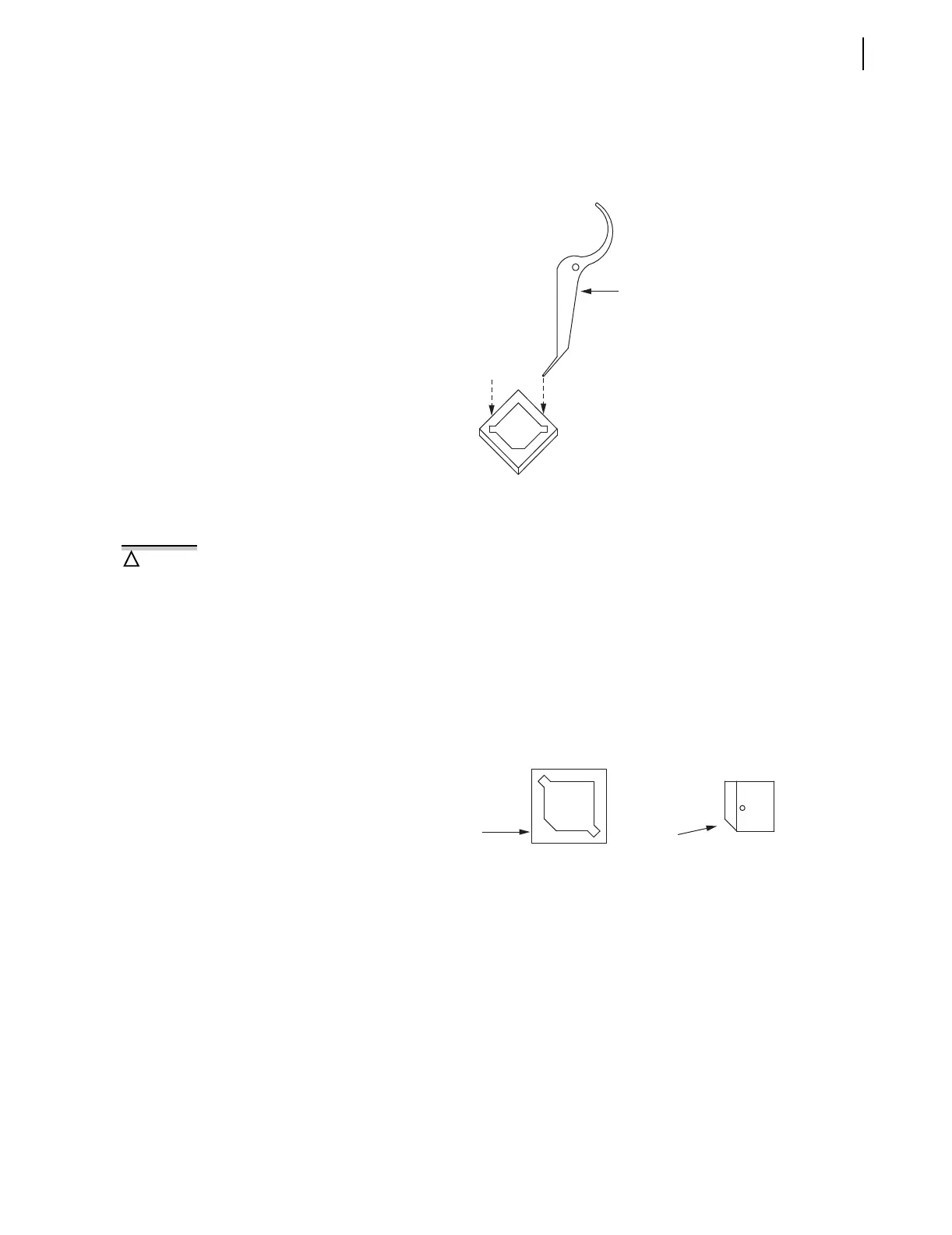
Figure B.2 Insertion of the Extraction Tool in the EPROM Socket
Reference: AMP Instruction Sheet 408-9695 (dated May 18,
1994, Rev. B).
Step 14. Remove the extraction tool from the slot, and insert it into the
opposite extraction slot.
Step 15. With a slight downward pressure, rotate the extraction tool
away from the EPROM socket until the other side of the
EPROM starts to lift away from the EPROM socket.
Step 16. Alternate between the two extraction slots, and gently lift the
EPROM from the socket.
Step 17. Carefully place the new EPROM in the socket, and apply even,
firm pressure to fully engage it in the socket.
Figure B.3 Proper Orientation of the EPROM and EPROM Socket
Step 18. Slide the drawout assembly into the relay chassis.
Step 19. Reconnect the analog signal ribbon cable.
Step 20. Replace the relay front panel.
Step 21. Replace the rear-panel communications cable.
Step 22. With breaker control disabled, turn relay power on.
Step 23. If the EN LED is illuminated, proceed to Step 10 below.
Verify proper orientation of the new
EPROM in the socket before applying
pressure to engage it. Note the
orientation indication provided by
the notched inside socket corner and
the notched corner.
!
CAUTION
Notched Inside
Socket Corner
U8
Notched EPROM
Corner