3.5
Date Code 20110408 Instruction Manual SEL-551 Relay
Relay Elements and Logic
Local Control Switches
Local Control Switches
Local control switches emulate traditional panel switches and are operated via
the front-panel keyboard/display only (see Section 6: Front-Panel Interface;
{CNTRL} pushbutton).
The switch representation in this figure is derived from the standard:
Graphics Symbols for Electrical and Electronics Diagrams IEEE Std 315-1975,
CSA Z99-1975, ANSI Y32.2-1975, 4.11 Combination Locking and Nonlocking Switch,
Item 4.11.1
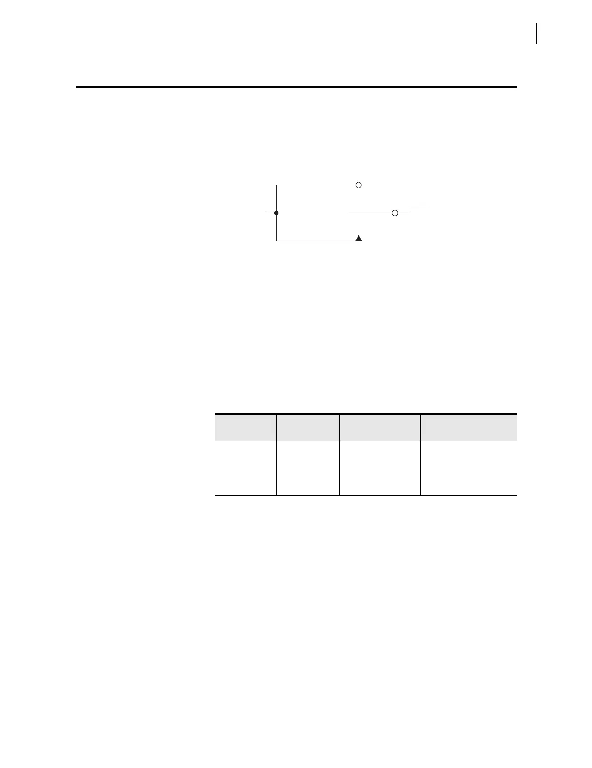
Figure 3.2 Local Control Switches Drive Local Bits LB1–LB8
The output of the local control switch in Figure 3.2 is a Relay Word bit (local
bit LBn, n = 1–8). These local bits are used in SEL
OGIC control equations. For
a given local control switch, the local control switch positions are enabled by
making corresponding label settings.
Each local control switch also has a corresponding “name” label setting
NLBn. Label settings are made with serial port command SET T and viewed
with serial port command SHO T (see Section 4: Setting the Relay and
Section 5: Serial Port Communications and Commands).
Any given local control switch can be configured to be one of the following
three switch types:
➤ ON/OFF
➤ OFF/MOMENTARY
➤ ON/OFF/MOMENTARY
Table 3.3 Correspondence Between Local Control Switch Positions and
Label Settings
Switch
Position
Label
Setting
Setting
Definition
Logic
State
ON SLBn “Set” Local bit LBn logical 1
OFF CLBn “Clear” Local bit LBn logical 0
MOMENTARY PLBn “Pulse” Local bit LBn logical 1 for
one processing interval
Logical 1
LBn
(n = 1 through 16)
ON Position
(Maintained Logical 1
Position)
OFF Position
(Maintained Logical 0 Position)
MOMENTARY Position
(Logical 1 for One Processing Interval)
Relay
Word
Bit