2.16
SEL-551 Relay Instruction Manual Date Code 20110408
Installation
Circuit Board Jumpers and Battery
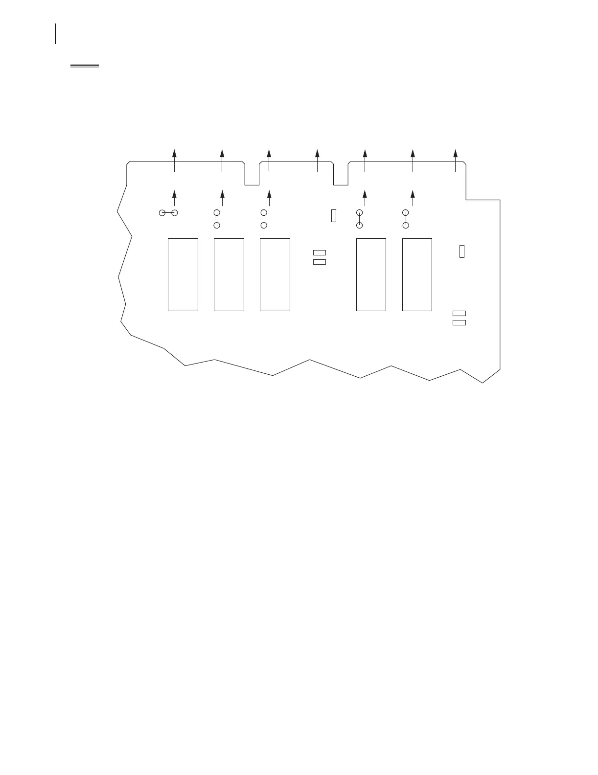
In Figure 2.15, note that the ALARM output contact is a b-type output contact
and the other output contacts are all a-type output contacts. This is how these
jumpers are configured in a standard relay shipment. Refer to Figure 3.23 for
examples of output contact operation for different output contact types.
Figure 2.15 Input and Output Jumper Locations (SEL-551 Relay With the Conventional Terminal Blocks With
Jumper-Selectable Control Input Voltage Option)
Password and
Breaker Jumpers
Password and Breaker jumpers are on the front edge of the relay main board
between the front-panel LEDs and the control pushbuttons. Remove the relay
front panel to change them.
Put Password jumper JMP22 (left-most jumper) in place to disable serial port
and front-panel password protection. With the jumper removed, password
security is enabled. Set the passwords with the PASSWORD command (see
Section 5: Serial Port Communications and Commands).
Put Breaker jumper JMP24 (right-most jumper) in place to enable the serial
port commands OPEN, CLOSE, and PULSE. These commands are ignored
while JMP24 is removed. These commands are used primarily to assert output
contacts for circuit breaker control or testing purposes (see Section 5: Serial
Port Communications and Commands).
Rear-Panel
EIA-232 Serial
Communications Port
Voltage Jumper
(EIA-232 Option Only)
Jumper JMP14 in the SEL-551 is toward the rear of the main board, near the
rear-panel EIA-232 serial communications port. This jumper connects or
disconnects +5 Vdc to pin 1 on the EIA-232 serial communications port. In a
standard relay shipment, jumper JMP14 in the SEL-551 would be removed
(out-of-place) so that the +5 Vdc is not connected to pin 1 on the EIA-232
serial communications port. See Figure 5.1.
NOTE: For an SEL-551 relay with the
Plug-In Connectors Option, the output
contact types are fixed. There are no
jumpers available to change the
output contact types. Output contacts
OUT1–OUT4 are all a-type output
contacts. The ALARM output contact is
a b-type output contact.
Corresponding
Rear-Panel Labels
Main Board
Edge Connector
ALARM
ALARM
JMP5
A
B
JMP1
JMP6
A
B
JMP2
A
B
JMP3
JMP9
JMP10
A
B
YOUT2
OUT4
YOUT1
OUT3
XOUT2
OUT2
XOUT1
OUT1
YIN
IN2
XIN
IN1
JMP4
A
B
K5
K1K2
K3K4
JMP11
JMP7
JMP8