2.17
Date Code 20110408 Instruction Manual SEL-551 Relay
Installation
Circuit Board Jumpers and Battery
Output Contact OUT4
Control Jumper
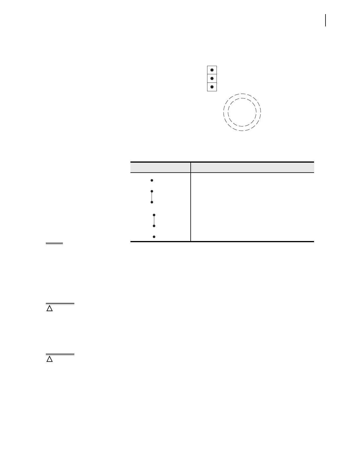
Refer to Figure 2.16 and Table 2.2. Main board jumper JMP13 controls the
operation of output contact OUT4. It provides the option of a second alarm
output contact by changing the signal that drives output contact OUT4.
Figure 2.16 Output Contact OUT4 Control Jumper Location
See Figure 3.23. If jumper JMP13 is in position ALARM and both output contacts
OUT4 and ALARM are the same output contact type (a or b), they will be in the
same state (closed or open). If jumper JMP13 is in position ALARM and output
contacts OUT4 and ALARM are different output contact types (one is an a and
one is a b), they will be in opposite states (one is closed and one is open).
Clock Battery
A lithium battery powers the relay clock (date and time) if the external dc
source is lost or removed. The battery is a 3 V lithium coin cell. At room
temperature (25°C), the battery will nominally operate for 10 years at rated
load.
If the dc source is lost or disconnected, the battery discharges to power the
clock. When the relay is powered from an external source, the battery only
experiences a low self-discharge rate. Thus, battery life can extend well
beyond the nominal 10 years because the battery rarely has to discharge after
the relay is installed. The battery cannot be recharged.
If the battery voltage is out-of-tolerance, an automatic status message is sent
to the serial port and the front-panel display.
To change the battery, take the following steps:
Step 1. De-energize the relay.
Step 2. Remove the three front-panel screws and the relay front panel.
Step 3. Disconnect the analog signal ribbon cable from the underside
of the relay main board.
Table 2.2 Required Position of Jumper JMP13 for Desired Output Contact
OUT4 Operation
Position Output Contact OUT4 Operation
Regular output contact OUT4 (operated by Relay Word bit
OUT4). Jumper JMP13 comes in this position in a standard
relay shipment.
Extra Alarm output contact (operated by alarm logic/cir-
cuitry). Relay Word bit OUT4 does not have any effect on
output contact OUT4 when jumper JMP13 is in this position.
ALARM
YOUT2
Clock
Battery
JMP13
3
2
1
NOTE: Some initial shipments of
SEL-551 relays did not have this
jumper JMP13 feature.
There is danger of explosion if the
battery is incorrectly replaced.
Replace only with Ray-O-Vac
®
no.
BR2335 or equivalent recommended
by manufacturer. Dispose of used
batteries according to the
manufacturer’s instructions.
!
CAUTION
The relay contains devices sensitive
to Electrostatic Discharge (ESD).
When working on the relay with the
front panel removed, work surfaces
and personnel must be properly
grounded or equipment damage may
result.
!
CAUTION