1.7
Date Code 20110408 Instruction Manual SEL-551 Relay
Introduction and Specifications
CT Saturation Protection
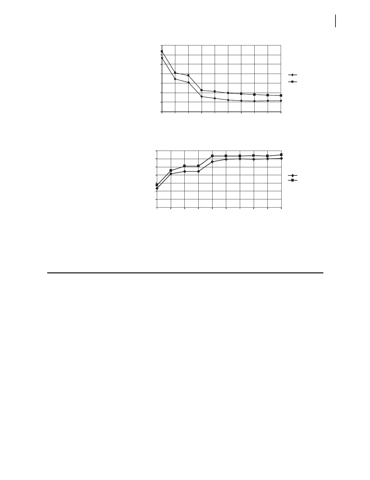
Figure 1.4 SEL-551 Instantaneous Overcurrent Element Pickup Time Curve
Figure 1.5 SEL-551 Relay Instantaneous Overcurrent Element Reset Time
Curve
CT Saturation Protection
The SEL-551 phase instantaneous overcurrent elements normally operate
using the output of a cosine filter algorithm. During heavy fault currents when
the relay detects severe CT saturation, the overcurrent elements can operate on
the adaptive current algorithm.
The adaptive current algorithm is only used for phase instantaneous
overcurrent elements if and only if the corresponding pickup setting is greater
than eight times the nominal phase current. For example, if 50P1P = 45 A (in a
5 Amp nominal phase current relay), then the 50P1 element operates on the
adaptive current algorithm. However, if 50P1P = 35 A, then the 50P1 element
operates on the output of a cosine filter algorithm. No other overcurrent
elements use the adaptive current algorithm.
Based on the level of a “harmonic distortion index,” the adaptive current is
either the output of the cosine filter or the output of the bipolar peak detector.
When the harmonic distortion index exceeds the fixed threshold that indicates
severe CT saturation, the adaptive current is the output of the bipolar peak
detector. When the harmonic distortion index is below the fixed threshold, the
adaptive current is the output of the cosine filter.
The cosine filter provides excellent performance in removing dc offset and
harmonics. However, the bipolar peak detector has the best performance in
situations of severe CT saturation when the cosine filter magnitude estimation
0
0.2
0.4
0.6
0.8
1
1.2
1.4
1.2 2 3 4 5 6 7 8 9
10
Minimum
Maximum
Applied Current (Multiples of Pickup Setting)
Pickup Time (Cycles)
0
0.2
0.4
0.6
0.8
1
1.2
1.4
1.2 2 3 4 5 6 7 8 9
10
Applied Current (Multiples of Pickup Setting)
Reset Time (Cycles)
Minimum
Maximum