8.9
Date Code 20110408 Instruction Manual SEL-551 Relay
Testing and Troubleshooting
Acceptance Testing
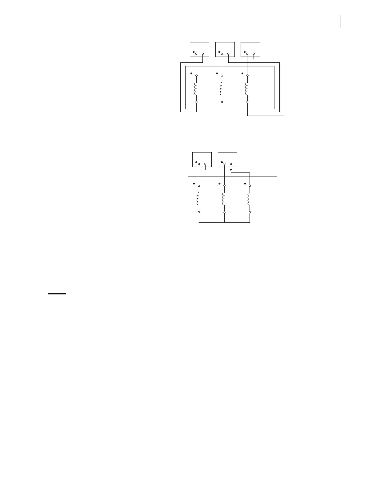
Figure 8.3 Test Connections for Balanced Load With Three-Phase Current
Sources
Figure 8.4 Test Connections for Balanced Load With Two-Phase Current
Sources
Instantaneous
Overcurrent Elements
Step 1. Purpose:
Determine the expected instantaneous overcurrent element
pickup value.
Method:
a. Execute the SHO command via the relay front panel or
serial port and verify the setting (i.e., SHO 50P1P
<Enter>).
Step 2. Purpose:
Display the appropriate Relay Word bit on the front-panel
LEDs.
Method:
a. Execute the TARGET command (i.e., TAR 2
<Enter>).
The SEL-551 now displays the state of several
overcurrent elements on the front-panel LED and LCD
display.
101
(Z01)
102
(Z02)
IA
104
(Z04)
103
(Z03)
IB
106
(Z06)
105
(Z05)
IC
SEL-551
(partial)
Current Current Current
101 = Terminal Block
(Z01) = Connectorized
101
(Z01)
102
(Z02)
IA
104
(Z04)
103
(Z03)
IB
106
(Z06)
105
(Z05)
IC
SEL-551
(partial)
Current Current
101 = Terminal Block
(Z01) = Connectorized
NOTE: This example tests the 50P1
phase overcurrent element. Use the
same procedure to test all
instantaneous overcurrent elements
for each phase.