3.45
Date Code 20110408 Instruction Manual SEL-551 Relay
Relay Elements and Logic
Demand Ammetering
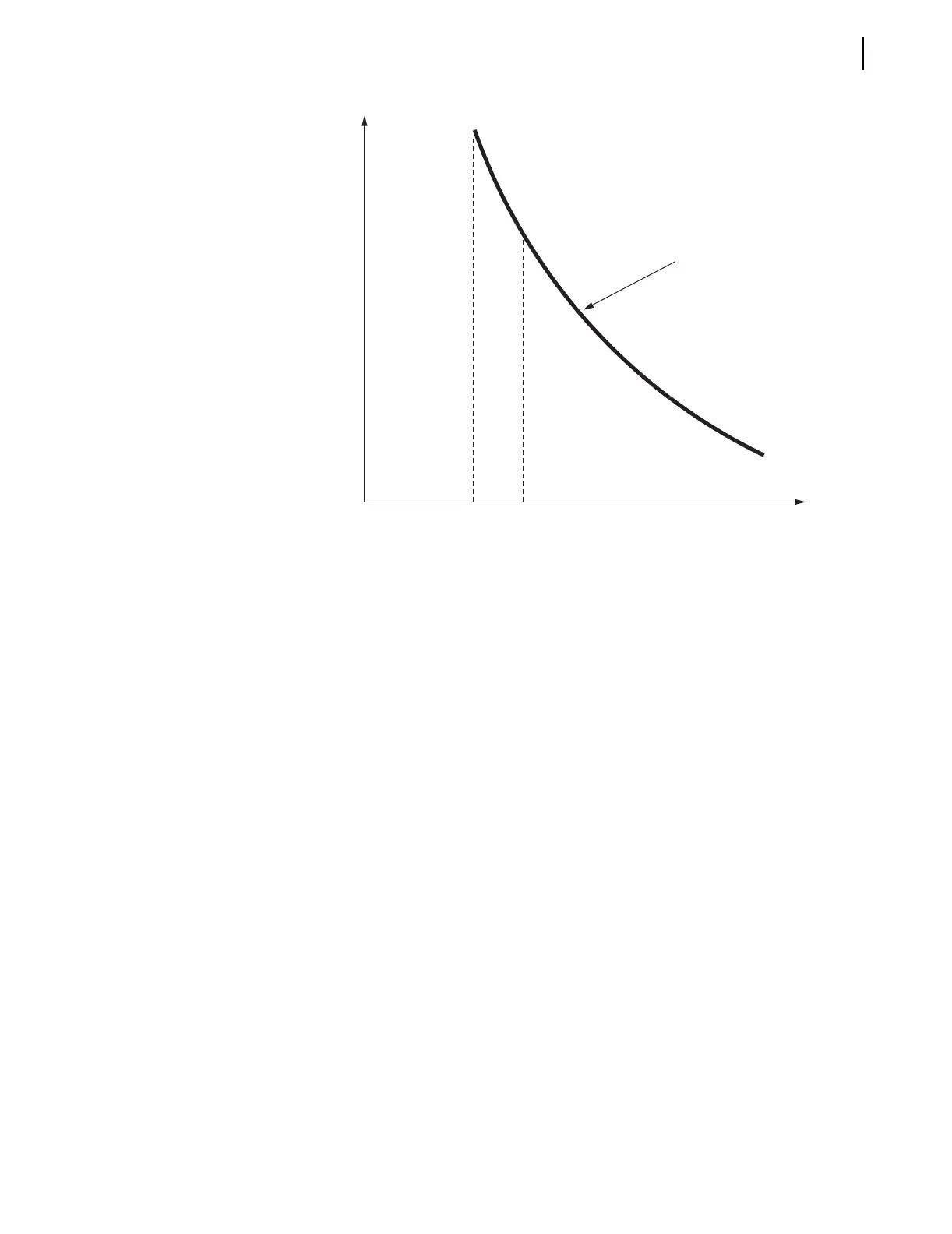
Figure 3.27 Raise Pickup of Residual Ground Time-Overcurrent Element for
Unbalance Current
Residual Ground Demand Current Below Pickup GDEMP
When unbalance current I
G
is low, unbalance demand current I
G(DEM)
is
below corresponding demand pickup GDEMP = 1.00 A secondary, and Relay
Word bit GDEM is deasserted to logical 0. This results in SEL
OGIC control
equation torque control setting 51G1TC being in the state:
51G1TC = !GDEM + GDEM * 50G1 = NOT(GDEM) + GDEM * 50G1
=NOT(logical 0) + (logical 0) * 50G1 = logical 1
Thus, the residual ground time-overcurrent element 51G1T operates on its
standard pickup:
51G1P = 1.50 A secondary
If a ground fault occurs, the residual ground time-overcurrent element 51G1T
operates with the sensitivity provided by pickup 51G1P = 1.50 A secondary.
The thermal demand ammeter, even with setting DMTC = 5 minutes, does not
respond fast enough to the ground fault to make a change to the effective
residual ground time-overcurrent element pickup—it remains at 1.50 A
secondary. Demand meters respond to more “slow moving” general trends.
Residual Ground Demand Current Goes Above Pickup GDEMP
When unbalance current I
G
increases, unbalance demand current I
G(DEM)
follows, going above corresponding demand pickup GDEMP = 1.00 A
secondary, and Relay Word bit GDEM asserts to logical 1. This results in
SEL
OGIC control equation torque control setting 51G1TC being in the state:
51G1TC = !GDEM + GDEM * 50G1 = NOT(GDEM) + GDEM * 50G1 =
NOT(logical 1) + (logical 1) * 50G1 = logical 0 + 50G1 = 50G1
51G1T
I
G
(Residual)
51G1P
= 1.50
t
50G1P
= 2.30