3.3
Date Code 20110408 Instruction Manual SEL-551 Relay
Relay Elements and Logic
Optoisolated Inputs
Optoisolated Inputs
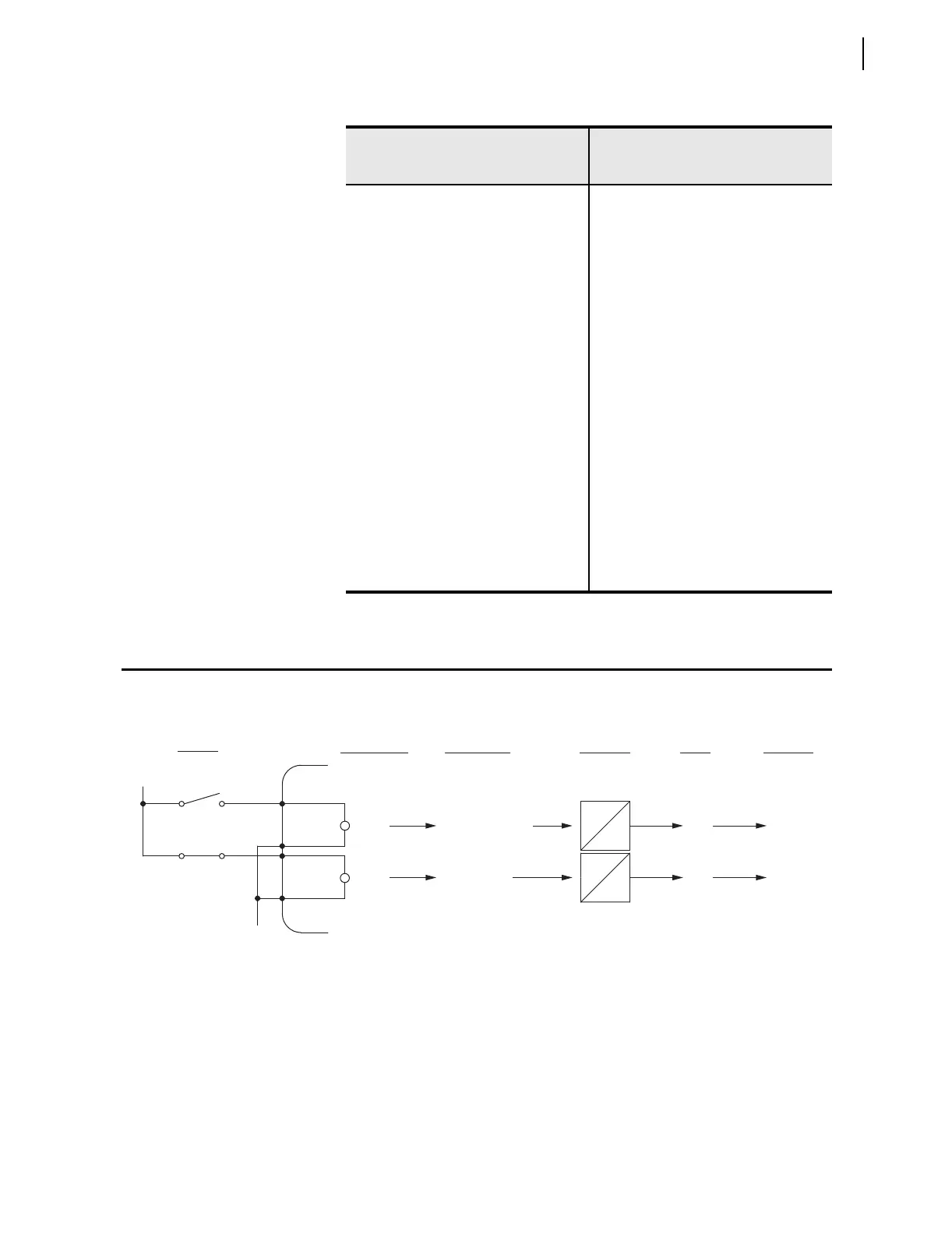
Figure 3.1 Example Operation of SEL-551 Optoisolated Inputs
Relay Word bits IN1 and IN2 follow optoisolated inputs IN1 and IN2,
respectively. See Figure 3.1 for the optoisolated inputs available with the SEL-
551 relay. This figure gives an example of an energized and de-energized
optoisolated input and corresponding Relay Word bit states. Note the built-in
pickup and dropout times of 0.25 cycles for energization or de-energization
debounce.
Table 3.2 Processing Order of Relay Elements and Logic (Top to Bottom)
Relay Elements and Logic
(corresponding SEL
OGIC Control
Equations listed in parentheses)
Resultant Relay Word Bits
Optoisolated Inputs IN1, IN2
Local Control Switches LB1–LB8
Remote Control Switches RB1–RB8
Demand Ammetering PDEM, NDEM, GDEM, QDEM
Instantaneous Overcurrent Elements 50P1–50P6, 50A, 50B, 50C, 50N1,
50N2, 50G1, 50G2, 50Q1, 50Q2
Time-Overcurrent Elements
(51P1TC, 51P2TC, 51N1TC,
51G1TC, 51Q1TC, 51Q2TC)
51P1, 51P2, 51N1, 51G1, 51Q1,
51Q2, 51P1T, 51P2T, 51N1T,
51G1T, 51Q1T, 51Q2T, 51P1R,
51P2R, 51N1R, 51G1R, 51Q1R, 51Q2R
Trip Logic (TR, ULTR) TRIP
Close Logic (52A, CL, ULCL)
Reclosing Relay (79RI, 79RIS, 79DTL,
79DLS, 79SKP, 79STL, 79BRS, 79SEQ)
CLOSE, CF, 79RS, 79CY, 79LO,
SH0, SH1, SH2, SH3, SH4
SEL
OGIC Variables/Timers (SV1–SV14) SV1–SV14, SV5T–SV14T
Output Contacts (OUT1–OUT4) OUT1–OUT4
Display Points (DP1–DP8)
Event Report Triggers (ER1, ER2)
Relay
Word
Bits States
Relay
Word Bit
Input States
Optoisolator
Inputs
Optoisolator
States
Example
Switch Debounce
Built-in
Timers
energized
de-energized
IN2
IN1
IN2
IN1
logical 1
logical 0
(–)
(+)
open
closed
CYC
0.25
CYC
0.25
CYC
0.25
CYC
0.25