3.9
Date Code 20110408 Instruction Manual SEL-551 Relay
Relay Elements and Logic
Instantaneous Overcurrent Elements
For example, if 50P1P = 45 A (in a 5 A nominal phase current relay), the I
P
input into the 50P1 logic is the maximum phase current output of the adaptive
current algorithm. If 50P1P = 35 A, then the I
P
input into the 50P1 logic is the
maximum phase current output of a cosine filter algorithm.
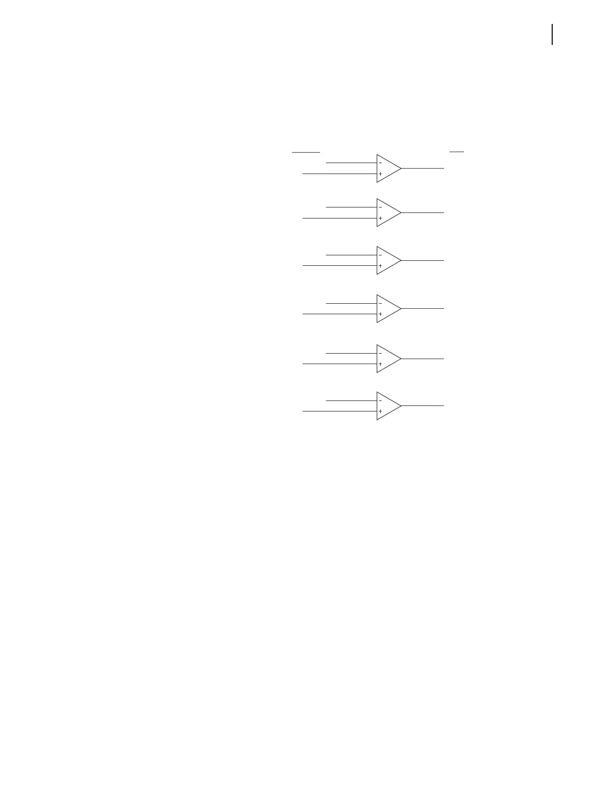
Figure 3.4 Phase Instantaneous Overcurrent Elements 50P1–50P6
Example 50P1 element operation:
I
P
> pickup setting 50P1P, then Relay Word bit 50P1 = logical 1
I
P
≤ pickup setting 50P1P, then Relay Word bit 50P1 = logical 0
If pickup setting 50P1P is set to 50P1P = OFF, then element 50P1 is disabled.
Relay Word bit 50P1 equals logical 0 at all times.
The other five phase instantaneous overcurrent elements (50P2–50P6) operate
similarly.
Single-Phase
Instantaneous
Overcurrent Elements
Single-phase instantaneous overcurrent elements (50A, 50B, and 50C) are
available (see Figure 3.5). The pickup setting (50ABCP, used for all three
single-phase elements) is compared to the magnitude of the single-phase
current (I
A
, I
B
, and I
C
). The phase current is normally the output of the cosine
filter algorithm, but during CT saturation the phase current can be the output
of the adaptive current algorithm if the pickup setting is greater than eight
times nominal phase current.
For example, if 50ABCP = 45 A (in a 5 A nominal phase current relay), the I
A
input into the 50A logic is the maximum phase A adaptive current algorithm,
the I
B
input into the 50B logic is the maximum phase B adaptive current
algorithm, and the I
C
input into the 50C logic is the maximum phase C
adaptive current algorithm. If 50ABCP = 35 A, the I
A
input into 50A logic is
the maximum phase A current output of cosine filter algorithm, the I
B
input
Relay
Word
Bits
Settings/
Currents
50P1P
I
P
50P2P
50P3P
50P4P
50P5P
50P6P
(max. phase)
I
P
(max. phase)
I
P
(max. phase)
I
P
(max. phase)
I
P
(max. phase)
I
P
(max. phase)
50P1
50P2
50P3
50P4
50P5
50P6