4.14
SEL-551 Relay Instruction Manual Date Code 20110408
Setting the Relay
Relay Word Bit Setting Reference Information
Relay Word Bit Setting Reference Information
Relay Word bits are used in SELOGIC control equation settings. See Section 3:
Relay Elements and Logic for SEL
OGIC control equations details and
examples. SEL
OGIC control equation settings can also be set directly to 1
(logical 1) or 0 (logical 0).
The Relay Word bit row numbers correspond to the row numbers used in the
TAR command (see TAR Command (Target) on page 5.20).
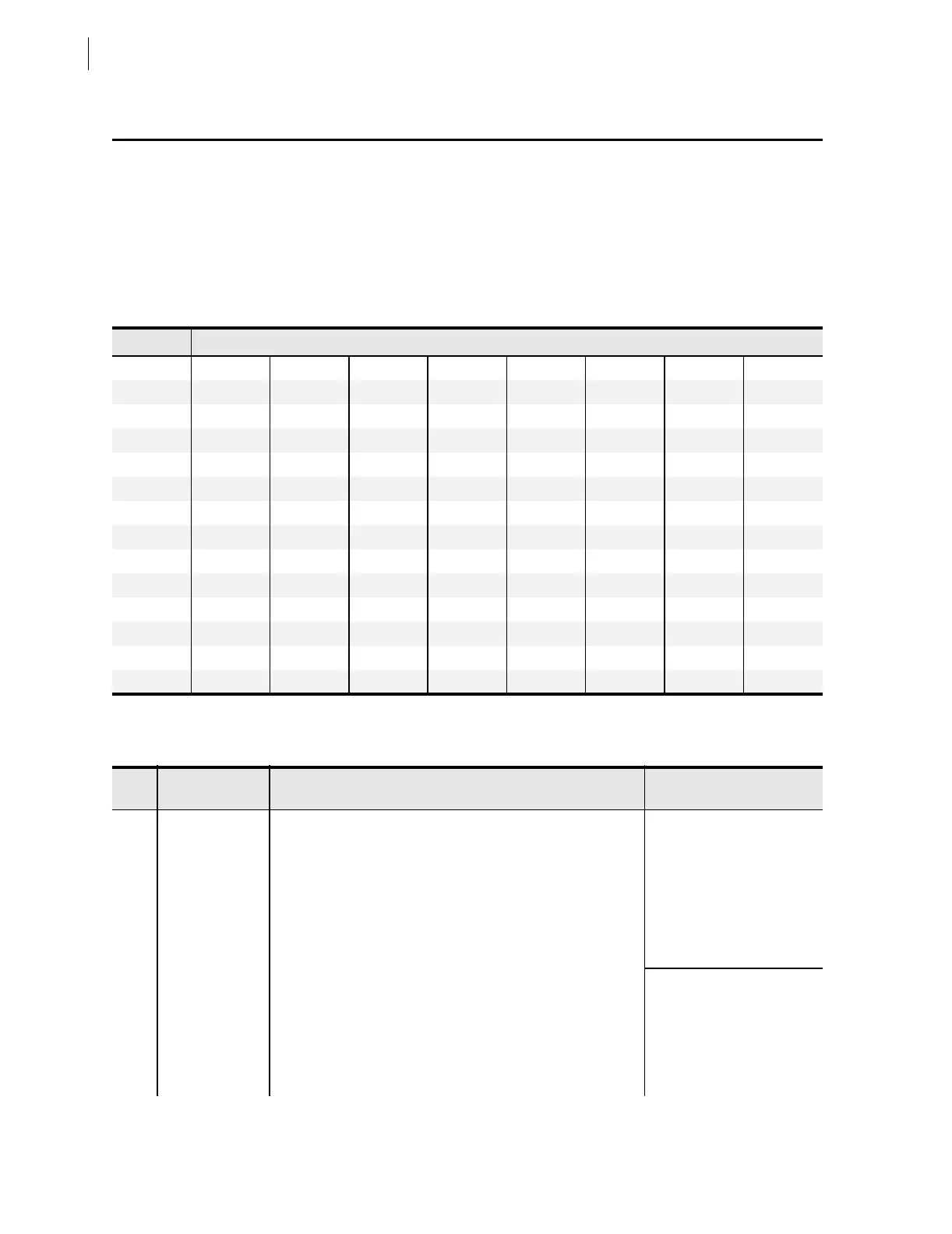
Ta b le 4 . 5 S E L- 5 5 1 R el ay Word B i ts
Row
a
a
Row 0 used for front-panel LEDs and TAR command as shown in Ta bl e 5 . 6 . Row 0 targets are not available for SELOGIC control equations.
SEL-551 Relay Word Bits
1
51P1 51P2 51N1 51G1 51P1T 51P2T 51N1T 51G1T
2
51Q1 51Q2 51Q1T 51Q2T 50P1 50P2 50P3 50P4
3
50P5 50P6 50N1 50N2 50G1 50G2 50Q1 50Q2
4
50A 50B 50C IN1 IN2 OC CC CF
5
LB1 LB2 LB3 LB4 LB5 LB6 LB7 LB8
6
RB1 RB2 RB3 RB4 RB5 RB6 RB7 RB8
7
SV1 SV2 SV3 SV4 SV5 SV6 SV7 SV8
8
SV9 SV10 SV11 SV12 SV13 SV14 *
b
b
Reserved for future use.
*
b
9
79RS 79CY 79LO SH0 SH1 SH2 SH3 SH4
10
TRIP CLOSE 51P1R 51P2R 51N1R 51G1R 51Q1R 51Q2R
11
SV5T SV6T SV7T SV8T SV9T SV10T SV11T SV12T
12
SV13T SV14T *
b
ALARM OUT1 OUT2 OUT3 OUT4
13
PDEM NDEM GDEM QDEM TRGTR *
b
*
b
*
b
TAR 14
*
b
*
b
*
b
*
b
*
b
*
b
*
b
*
b
Ta b le 4 . 6 Re la y W o rd B i t D e f i n i t io n s (Sheet 1 of 4)
Row Bit Definition
Primary
Application
1 51P1 Maximum phase current above pickup setting 51P1P
for phase time-overcurrent element 51P1T (see Figure 3.9)
Event report triggering,
Testing
51P2 Maximum phase current above pickup setting 51P2P
for phase time-overcurrent element 51P2T (see Figure 3.9)
51N1 Neutral ground current (channel IN) above pickup setting 51N1P for
neutral ground time-overcurrent element 51N1T (see Figure 3.10)
51G1 Residual ground current above pickup setting 51G1P for residual
ground time-overcurrent element 51G1T (see Figure 3.11)
51P1T 1st phase time-overcurrent element timed out (see Figure 3.9) Tripping
51P2T 2nd phase time-overcurrent element timed out (see Figure 3.9)
51N1T Neutral ground time-overcurrent element timed out
(see Figure 3.10)
51G1T Residual ground time-overcurrent element timed out
(see Figure 3.11)