F.3
Date Code 20110408 Instruction Manual SEL-551 Relay
Setting Negative-Sequence Overcurrent Elements
Coordinating Negative-Sequence Overcurrent Elements
feeder relay in this example. Note that the overcurrent element labels in the
example are not the same as the labels of the corresponding SEL-551
overcurrent elements.
Coordination
Guidelines
1. Start with the furthest downstream negative-sequence
overcurrent element (e.g., distribution feeder relay in a
substation).
2. Identify the phase overcurrent device (e.g., line recloser, fuse)
downstream from the negative-sequence overcurrent element
that is of greatest concern for coordination.
This is usually the phase overcurrent device with the longest
clearing time.
3. Consider the negative-sequence overcurrent element as an
“equivalent” phase overcurrent element.
Derive pickup, time dial (lever), curve type, or time-delay
settings for this “equivalent” element to coordinate with the
downstream phase overcurrent device, as any phase
coordination would be performed.
Load considerations can be disregarded when deriving the
“equivalent” phase overcurrent element settings.
4. Multiply the “equivalent” phase overcurrent element pickup
setting by √
3 to convert it to the negative-sequence overcurrent
element pickup setting in terms of 3I
2
current.
Any time dial (lever), curve type, or time delay calculated for
the “equivalent” phase overcurrent element is also used for the
negative-sequence overcurrent element with no conversion
factor applied.
5. Set the next upstream negative-sequence overcurrent element to
coordinate with the first downstream negative-sequence
overcurrent element and so on.
Again, coordination is not influenced by load considerations.
Coordination Example
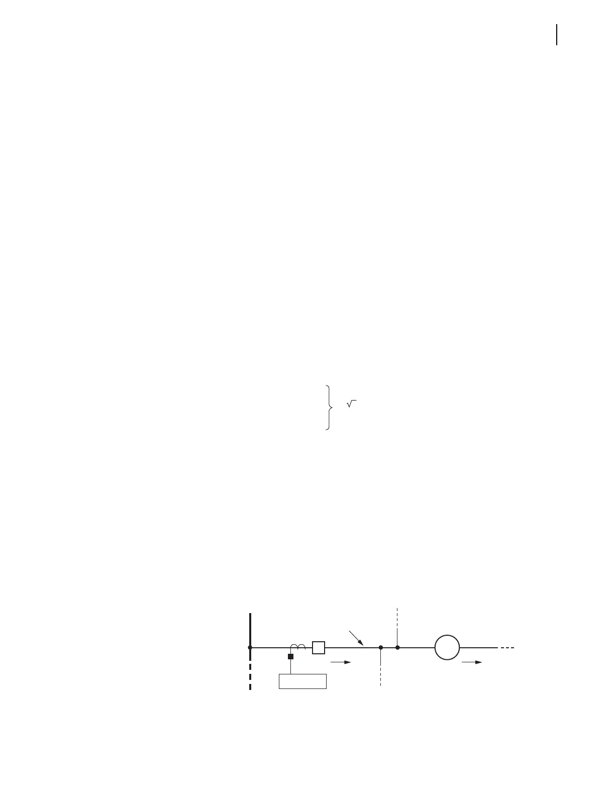
In Figure F.2 the phase and negative-sequence overcurrent elements of the
feeder relay (51F and 51QF, respectively) must coordinate with the phase
overcurrent element of the line recloser (51R).
Figure F.2 Distribution Feeder Protective Devices
Negative-
sequence
overcurrent
element
pickup
=
3 • ("equivalent" phase overcurrent element pickup)
Feeder Relay
Feeder
I
R
Bus
I
F
51F, 51QF
R
Line Recloser
52
51R