4
Installation
Braking resistors
Operating Instructions – MOVIDRIVE
®
modular
107
4.8.2 Protection against thermal overload of the braking resistor
INFORMATION
Guards for supply modules with nominal power larger than 10kW
It is not permitted to separate the connection between power supply module and
braking resistor. Isolating protection devices, such as fuses or miniature circuit break-
ers are not permitted.
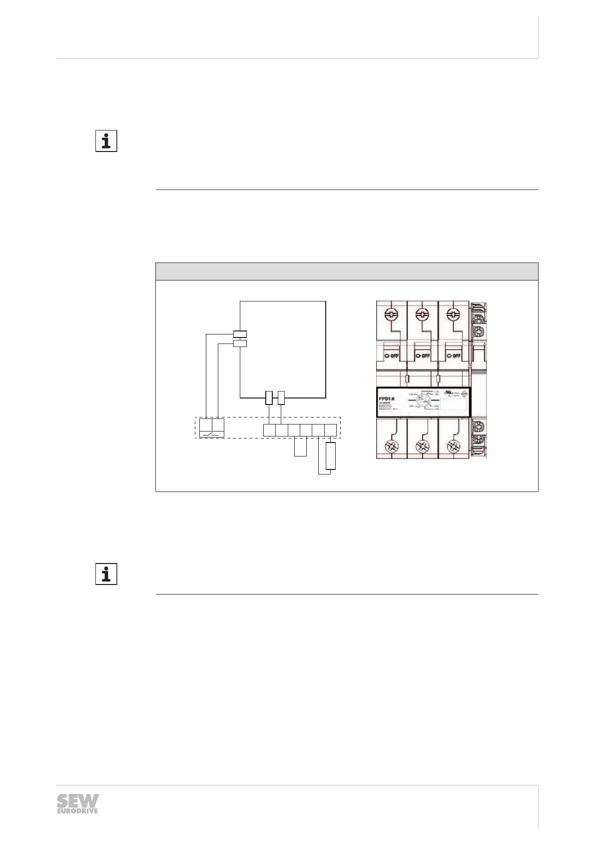
External thermal circuit breaker TCB
MDP90A power supply module 10 kW
If an external TCB thermal circuit breaker is used, the following connection applies.
Connection
1 3 5
2 4 6
12
24
23
11
MDP90A
X7:2 -Temp_R
X7:1 +Temp_R
X3 +R
X3 -R
23 24
5 2 1 4 3 6
[1]
[2]
9007218815961227
[1] TCB thermal circuit breaker
[2] Braking resistor
INFORMATION
The polarity of the connections 5 (+R) and 2 (-R) must be strictly adhered to during
connection of the TCB circuit breaker to the inverter.
• If the thermal circuit breaker trips, the signal contact is set (23-24 connection is
opened) and evaluated in the power supply module.
• The connection between power supply module and braking resistor is disconnec-
ted.
• This does not require a response by the PLC.
• It is not required to disconnect the supply system connection with an external
switching device.
• If the thermal circuit breaker trips, the power supply module switches all axis mod-
ules to "Output stage inhibit".
24748536/EN – 11/2017
 Loading...