6
Operation
Faults at the power supply module
Operating Instructions – MOVIDRIVE
®
modular
163
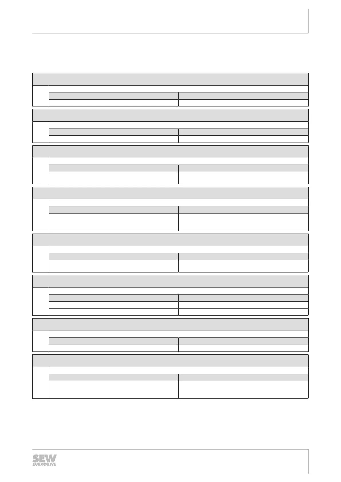
6.4 Faults at the power supply module
6.4.1 Fault 49 Power supply module
Subfault: 49.1
Description: Unknown supply unit
Response: Remote – critical fault
Cause Measure
Failed to identify supply unit Contact the SEW-EURODRIVE Service.
Subfault: 49.2
Description: EEPROM memory – hardware faulty
Response: Remote – critical fault
Cause Measure
EEPROM cannot be read; initialization error. Contact the SEW-EURODRIVE Service.
Subfault: 49.3
Description: Internal voltage supply
Response: Remote – critical fault
Cause Measure
At least one internal supply voltage is faulty. Switch the power off and on again. Contact the
SEW‑EURODRIVE Service if the error is still present.
Subfault: 49.4
Description: DC 24 V supply voltage
Response: Remote – critical fault
Cause Measure
24V supply below min. specified 24V input voltage Check the 24V supply, switch power supply off and on again.
Contact the SEW‑EURODRIVE Service if the error is still
present.
Subfault: 49.5
Description: Fault in hardware component of analog to digital conversion
Response: Remote – critical fault
Cause Measure
Measured DC link values outside valid range or voltage supply
of transducers defective.
Contact the SEW-EURODRIVE Service.
Subfault: 49.6
Description: CRC error – power section data
Response: Remote – critical fault
Cause Measure
Device not yet calibrated. Contact the SEW-EURODRIVE Service.
Initialization error Contact the SEW-EURODRIVE Service.
Subfault: 49.7
Description: EEPROM data error
Response: Remote – critical fault
Cause Measure
Calibration data not plausible. Contact the SEW-EURODRIVE Service.
Subfault: 49.8
Description: DC link overvoltage
Response: Remote – critical fault
Cause Measure
Maximum permitted DC link voltage limit exceeded – Check brake chopper function, braking resistor, and regener-
ative energy.
– Check project planning of the axis system.
24748536/EN – 11/2017
 Loading...