8
Technical Data
Technical data for MDA and MDD axis modules
Operating Instructions – MOVIDRIVE
®
modular
218
Terminal designation Specification
Single-axis
module
Double-axis module
X15:15 X15:15_1
X15:15_2
X15:15 DC 12 V, I
max
= 500mA
1) AEH: Conductor end sleeve
INFORMATION
Freewheeling diode application
If inductive loads are connected to the digital outputs, you must install an external
protective element (freewheeling diode).
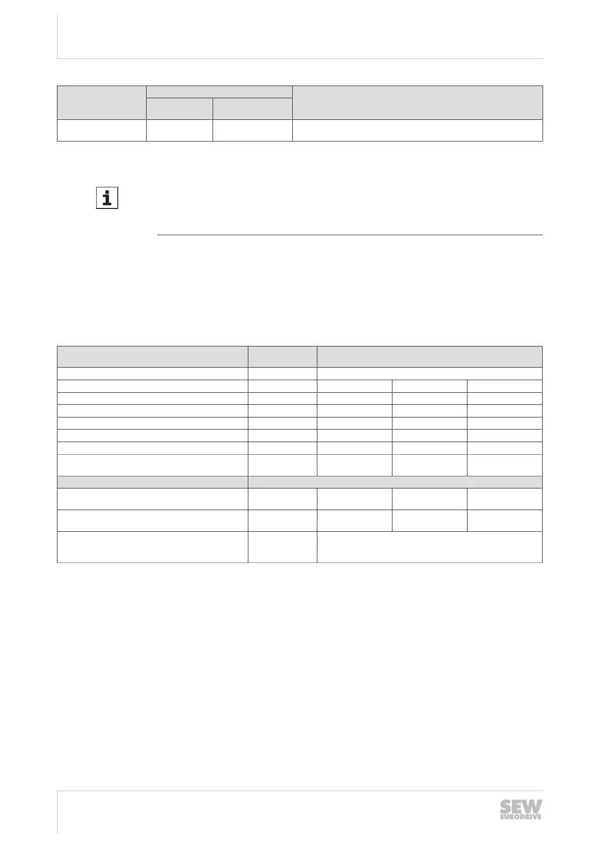
8.4.4 Electronics data – Drive safety functions
The table below shows the technical data of the application inverter relating to the in-
tegrated safety technology.
The safety-related digital inputs comply with type 3 according to IEC61131‑2.
Reference potential for the F_STO_P1 and F_STO_P2 is STO_M (contact at terminal
X6:2).
Terminal desig-
nation
General electronics data
Safety contact STO X6
Electrical data of inputs F_STO_P1, F_STO_P2 Minimum Typical Maximum
Input voltage range X6:1 and X6:3 DC-3V DC24 V DC30 V
Input capacitance – 1 nF 10 nF
Power consumption at DC 24 V – 200 mW 300 mW
Input voltage for ON status (STO) DC11 V – DC30 V
Input voltage for OFF status (STO) DC-3V – DC5 V
Permitted leakage current of the external safety con-
troller
– – 1 mA
Technical Data
Time from disconnecting the safety voltage until the
deactivation of the rotating field
– 1.5 ms 10 ms
Time from connecting the safety voltage until the ac-
tivation of the rotating field
– – 110 ms
Connection
Plug connector
- 1 core: 0.25 – 1.5 mm
2
- 2 cores: 0.25 – 0.5 mm
2
(Twin-AEH)
1)
1) AEH: Conductor end sleeve
24748536/EN – 11/2017
 Loading...