MX-2300/2700 N/G SIMULATION 7 – 95
<Description of item>
A to H: 1step=0.1mm
C to H: When the adjustment value is increased, the image loss is
increased.
* It is linked with items C to H of SIM50-6.
<Calculation formula>
SIDE1 adjustment value:
SIDE2 adjustment value:
*
1
: Correction value = (Measurement reference 10mm –
Lead edge image loss set value) x 10 x (Magnification ratio/
100)
Example of calculation: 140 = (100 – 30) x 10 x (200%/100)
*
2
: 2 = (Magnification ratio 200%/100)
If L4 = 0, do not make calculation of SIDE1, but adjust the value of
L5.
If L5 = 0, do not make calculation of SIDE2, but adjust the value of
L4.
If L4 = L5 = 0, the adjustment values of SIDE1 and SIDE2 are the
default values.
50-10
Purpose : Adjustment
Function (Purpose) : Used to adjust the print off-center for each
tray.
Image print center position adjustment
(Adjusted for each paper feed section.)
Section :–
Item : Image quality (Image position)
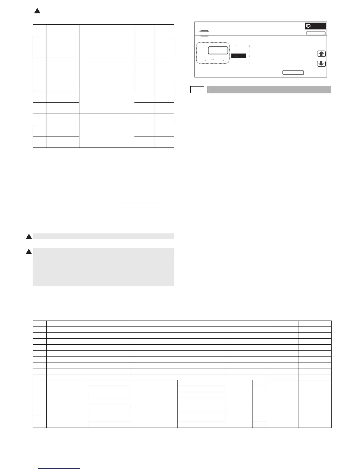
Operation/Procedure
1) Select the set item with [↑] and [↓] buttons.
The highlighted section of the set value is switched and dis-
played on the set setting area.
* If there is any item over [↑], an active display is made and
item is shifted.
If there is no item over [↑], the display grays out and the
operation is invalid.
If there is any item under [↓], an active display is made and
item is shifted.
If there is no item over [↓], the display grays out and the
operation is invalid.
2) Enter the set value with 10-key.
* When [C] key is pressed, the entered value is cleared.
3) When [EXECUTE] button is pressed, it is highlighted and print-
ing for adjustment is started with the current set value.
After completion of printing, [EXECUTE] button returns to the
normal display.
* When [↑], [↓], [OK] button, [COLOR], or [BLACK] key is pressed,
the data are saved to EEPROM and RAM.
* When [C], [CA], [SYSTEM SETTINGS], or [EXECUTE] button is
pressed during printing, the operation is interrupted.
* When the machine returns to the ready state after occurrence of
an interruption, self printing is resumed.
<Description of item>
Item Display item Description of item
Set
range
Default
value
A L4 Distance from the front
surface image lead edge to
the scale of 10mm (SPF
200%, unit 0.1mm)
0 to 999 —
B L5 Distance from the back
surface image lead edge to
the scale of 10mm (SPF
200%, unit 0.1mm)
0 to 999 —
C LEAD_EDGE
(SIDE1)
Image loss quantity setting
SIDE1
0 to 99 20
D FRONT_REAR
(SIDE1)
0 to 99 20
E TRAIL_EDGE
(SIDE1)
0 to 99 30
F LEAD_EDGE
(SIDE2)
Image loss quantity setting
SIDE2
0 to 99 20
G FRONT_REAR
(SIDE2)
0 to 99 20
H TRAIL_EDGE
(SIDE2)
0 to 99 30
L4
-
Correction value
*
1
2
*
2
Old set value
-
()
L5
-
Correction value *
1
2*
2
Old set value +
()
1
1
0
C:
A 0
B 0
C 20
D
20
L4
L5
LEAD_EDGE(SIDE1)
FRONT_REAR(SIDE1)
SIMULATION NO.50-07
LEAD EDGE ADJUSTMENT (SPF CALC.).
20
0 999
TEST
CLOSE
EXECUTE
Item Display item & Detail of display Item content Set range Default value Writing
A BK-MAG Main scan print magnification ratio BK 60 to 140 100 YES
B MFT Print off-center adjustment value (manual feed) 1 to 99 50 YES
C CS1 Print off-center adjustment value (Cassette 1) 1 to 99 50 YES
D CS2 Print off-center adjustment value (Cassette 2) 1 to 99 50 YES
E CS3 Print off-center adjustment value (Cassette 3) 1 to 99 50 YES
F CS4 Print off-center adjustment value (Cassette 4) 1 to 99 50 YES
G LCC Print off-center adjustment value (LCC) 1 to 99 50 YES
H ADU Print off-center adjustment value (ADU) 1 to 99 50 YES
I MULTI COUNT Print quantity 1 to 999 1 NO
J PAPER MFT Cassette select Manual feed 1 to 6 1 2 (CS1) NO
CS1 Cassette 1 2
CS2 Cassette 2 3
CS3 Cassette 3 4
CS4 Cassette 4 5
LCC LCC 6
K DUPLEX YES Duplex print select Selected 0 to 1 0 1 (NO) NO
NO Not selected 1
: Dec. 15 2005
1