MX-2300/2700 N/G ADJUSTMENTS 6 – 7
2) Open the PWB frame.
3) Enter SIM8-1 mode.
4) Select an output mode to be adjusted with the mode key and
the scroll key.
5) Check the relationship between the pin No. of the connector
CNMON on the MC/DV high voltage PWB and each adjust-
ment mode.
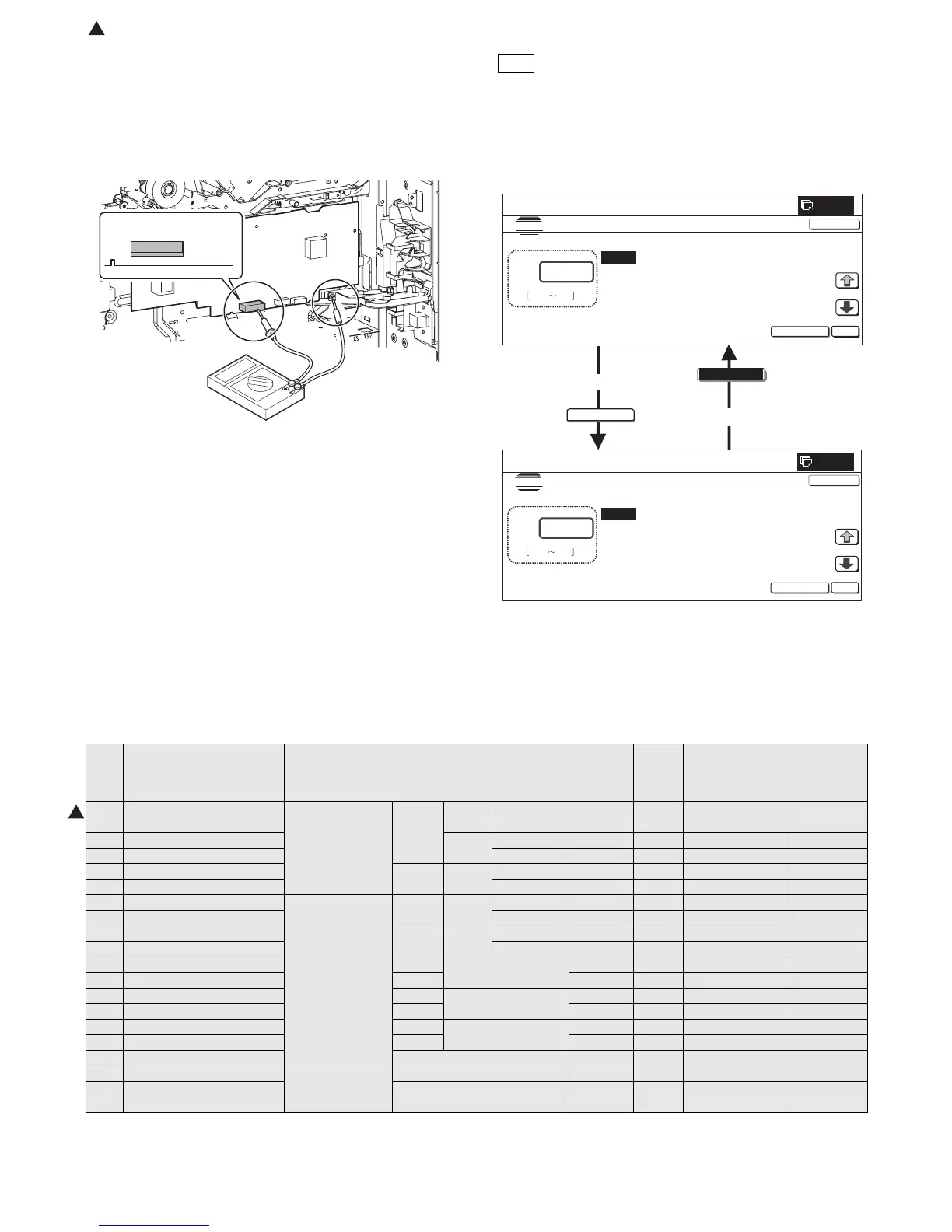
6) Apply a digital multi-meter to the connector CNMON pin on the
MC/DV high voltage PWB corresponding to the adjusted
mode.
7) Press [EXECUTE] key.
The developing bias voltage is outputted for 30sec.
8) Check the monitor voltage with the digital multi-meter.
If the monitor voltage is not in the range of the specified values
shown in the table above, change the adjustment value and
adjust again. If the specified value voltage is not obtained even
though the adjustment value is changed, the following parts
may be defective.
MC/DV high voltage PWB
PCU PWB
Developing unit
OPC drum unit
High voltage circuit electrode
4-C Transfer voltage adjustment
This adjustment must be executed in the following cases:
* When the TC high voltage power PWB is replaced.
* When U2 trouble occurs.
* When the PCU PWB is replaced.
* When EEPROM on the PCU PWB is replaced.
1) Enter SIM8-6 mode.
2) Select a mode to be adjusted with the scroll key.
3) Enter an adjustment value (specified value) and press [OK]
key.
By setting the default value (specified value), the specified
voltage is outputted.
When [EXECUTE] key is pressed, the transfer voltage is out-
putted.
CNMON
1
EXECUTE
EXECUTE
A:ġ
Aȇxxx
Bȇxxx
Cȇxxx
Ȉġ
TC1 LOW SPEEDġġCL K
Ȉġ TC1 MIDDLE SPEED CL K
Ȉġ TC1 LOW SPEED CL CMY
SIMULA TIONġ NO.08-06
THV SETTING AND OUTPUT
OK
TEST
EXECUTE
0
Dȇxxx Ȉ TC1 MIDDLE SPEED_CL CMY
CLOSE
A:ġ
Aȇxxx
Bȇxxx
Cȇxxx
Ȉ TC1 LOW SPEED CL K
Ȉ TC1 MIDDLE SPEED CL K
Ȉ TC1 LOW SPEED CLġ CMY
SIMULA TIONġ NO.08-06
THV SETTING AND OUTPUT
xxx
ġ 0 255
OK
Dȇxxx Ȉ TC1 MIDDLE SPEED_CL CMY
CLOSE
10-key
or after 30 sec.
Item Display Content
Setting
range
Default
value
Actual output
setting range
Default
value
Actual
output value
A TC1 LOW SPEED CL K Primary transfer
bias reference
value
COLOR K Low speed 0 to 255 232 –500V to 5000V 4500V
B TC1 MIDDLE SPEED CL K Middle speed 0 to 255 232 –500V to 5000V 4500V
C TC1 LOW SPEED CL CMY CMY Low speed 0 to 255 139 –500V to 5000V 2500V
D TC1 MIDDLE SPEED CL CMY Middle speed 0 to 255 139 –500V to 5000V 2500V
E TC1 LOW SPEED BW K BLACK K Low speed 0 to 255 232 –500V to 5000V 4500V
F TC1 MIDDLE SPEED BW K Middle speed 0 to 255 232 –500V to 5000V 4500V
G TC2 PLAIN CL SPX Secondary transfer
bias reference
value
COLOR Normal
paper
Front surface 51 to 255 100 2µA to 45µA 12.5µA
H TC2 PLAIN CL DPX Back surface 51 to 255 100 2µA to 45µA 12.5µA
I TC2 PLAIN BW SPX BLACK Front surface 51 to 255 90 2µA to 45µA 10µA
J TC2 PLAIN BW DPX Back surface 51 to 255 90 2µA to 45µA 10µA
K TC2 HEAVY1 CL SPX COLOR Heavy paper 51 to 255 69 2µA to 45µA 6µA
L TC2 HEAVY1 BW SPX BLACK 51 to 255 69 2µA to 45µA 6µA
M TC2 OHP CL COLOR OHP 51 to 255 60 2µA to 45µA 4µA
N TC2 OHP BW BLACK 51 to 255 60 2µA to 45µA 4µA
O TC2 ENVELOPE CL COLOR Envelope 51 to 255 184 2µA to 45µA 30µA
P TC2 ENVELOPE BW BLACK 51 to 255 184 2µA to 45µA 30µA
Q TC2 CLEANING Cleaning process 51 to 255 79 2µA to 45µA 8µA
R TC2 CLEAN LOW SPD Secondary transfer
cleaning bias
reference value
Low speed print 51 to 255 72 –50V to –1500 –200V
S TC2 CLEAN MIDDLE SPD Middle speed print 51 to 255 72 –50V to –1500V –200V
T TC2 CLEAN CLEANING Cleaning 51 to 255 156 –50V to –1500V –800V
1
: Dec. 15 2005
1