MX-2300/2700 N/G ADJUSTMENTS 6 – 9
If the adjustment is not completed normally, "ERROR" is displayed.
In that case, check the following sections for any abnormality. If any
abnormality is found, repair and adjust again.
If an error occurs, the adjustment result is not revised.
* Color image density sensor
* PCU PWB
* Image sensor calibration jig (standard reflection sheet dirt,
scratch, discoloration)
NOTE: Store the image sensor calibration jig under low tempera-
ture, low humidity and dark place.
5-B Color image density sensor, black image
density sensor, image registration sensor
adjustment
1) Enter SIM44-2 mode.
2) Press [EXECUTE] key.
The color image density sensor, the black image density sen-
sor, and the image registration sensor are automatically
adjusted.
After completion of the adjustment, the adjustment result is
displayed and [EXECUTE] key returns to the normal display.
If the adjustment is not completed normally, "ERROR" is dis-
played.
In that case, check the following sections for any abnormality.
If any abnormality is found, repair and adjust again.
If an error occurs, the adjustment result is not revised.
* Color image density sensor
* Black image density sensor
* Image registration sensor
* PCU PWB
* Transfer belt (dirt, scratch)
* Transfer belt cleaner
Display/Item Content
Adjustment
value range
Default
value
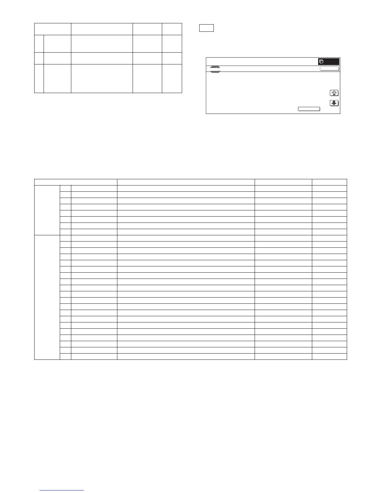
A PCS_CL
CARB OUT
Color image density sensor
LED current adjustment
target value
1 – 255 108
B PCS_CL
DARK
Color image density sensor
dark-voltage level
0 – 255 0
C PCS_CL
LED ADJ
Color image density sensor
LED current adjustment
target value (PCS CL CARB
OUT) registered LED current
level
1 – 255 21
0
SIMULATION NO.44-02
TEST
PROCON GAIN ADJUSTMENT
EXECUTE
PCS_CL LED ADJ xx
:
PCS_㧷 GRND xx
:
PCS_㧷 LED ADJ xx
:
PCS_K BELT MAX xx
:
PCS_CL DARK
xx
:
PCS_KBELTMIN xx
:
PCS_K DARK xx
:
PCS_KBELTDIF xx
:
1/4
CLOSE
Display/Item Content Adjustment value range Default value
PRO CON A PCS_CL LED ADJ Color image density sensor light emitting quantity adjustment value 1 – 255 21
B PCS _K LED ADJ Black image density sensor light emitting quantity adjustment value 1 – 255 21
C PCS_CL DARK Color image sensor dark voltage 0 – 255 0
D PCS_K DARK Black image density sensor dark voltage 0 – 255 0
E PCS_K GRND Belt base detection level when completion of Item B adjustment 0 – 255 0
F PCS_K BELT MAX Belt base detection level (Max.) 0 – 255 0
G PCS_K BELT MIN Belt base detection level (Min.) 0 – 255 0
H PCS_K BELT DIF Belt base detection level difference (Item F – Item G) 0 – 255 0
REGIST I REG_F LED ADJ Image registration sensor light emitting quantity adjustment value F 1 – 255 56
J REG_R LED ADJ Image registration sensor light emitting quantity adjustment value R 1 – 255 56
K REG_F DARK Image registration sensor dark voltage F 0 – 255 0
L REG_R DARK Image registration sensor dark voltage R 0 – 255 0
M REG_F GRND Belt base detection level when completion of Item I adjustment 0 – 255 0
N REG_R GRND Belt base detection level when completion of Item J adjustment 0 – 256 0
O REG_F BELTMAX Belt base detection level (Max.) F 0 – 255 0
P REG_F BELT MIN Belt base detection level (Min.) F 0 – 255 0
Q REG_F BELT DIF Belt base detection level difference (Item O – Item P) 0 – 255 0
R REG_R BELT MAX Belt base detection level (Max.) R 0 – 255 0
S REG_R BELT MIN Belt base detection level (Min.) R 0 – 255 0
T REG_R BELT DIF Belt base detection level difference (Item R – Item S) 0 – 255 0
U REG_F PATCH (K) Patch detection level F (K) 0 – 255 0
V REG_F PATCH (C) Patch detection level F (C) 0 – 255 0
W REG_F PATCH (M) Patch detection level F (M) 0 – 255 0
X REG_F PATCH (Y) Patch detection level F (Y) 0 – 255 0
Y REG_R PATCH (K) Patch detection level R (K) 0 – 255 0
Z REG_R PATCH (C) Patch detection level R (C) 0 – 255 0
AA REG_R PATCH (M) Patch detection level R (M) 0 – 255 0
AB REG_R PATCH (Y) Patch detection level R (Y) 0 – 255 0