MX-2300/2700 N/G TRANSFER SECTION L – 1
MX2700N
Service Manual
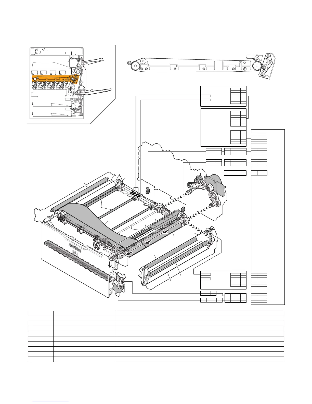
[L] TRANSFER SECTION
1. Electrical and mechanism relation diagram
Signal name Name Functions and operations
1TC_CMY Color trasnfer high voltage signal
1TC_K B/W transfer high voltage signal
1TNFD Waste toner full detection switch Waste toner full detection
1TUD_CL Transfer belt separation CL detection Color transfer roller position detection signal
1TUD_K Transfer belt separation BK detection B/W transfer roller position detection signal
1TURC Primary transfer separation clutch Transfer roller separation control clutch
2TC Secondary transfer high voltage signal
DVMK Developer drive motor (K) Transfer unit drive motor (Used together with the B/W developing drive roller)
WTNM Waste toner drive motor Stirs waste toner.
CN9
PHNR-3-H + BU03P-TR-P-H B30B-PHDSS-B
CN1 CN34
2-TC INT24V2 1
P-GND 2
CLR /TC_CLK# 4
/TC_DATA# 3
/TC_LD#
5
/HV_REM# 6
B6P-PH-K-S B40B-PADSS-B
B30B-PHDSS-B
CN1
B6P-PH-K-S
CN26
CN2
1TC_CL 3
HV_REM 7
MC_YMC 6
1TC_K 5
B32B-PHDSS-B
1TC_YMC 4
P-GND 2
INT24V2
1
B7P-PH-K-S
CN1
INT24V2 7
1TC-K
P-GND 6
1TC_YMC 4
1TC-CMY 1TC_K 3
MC_YMC 2
HV_REM 1
1TC_CL 5
B7P-PH-K-S
CN9
PHNR-3-H + BU03P-TR-P-H B30B-PHDSS-B
HV_REM#
6
5
4
3
2
1
/HV_DATA#
/HV_CLK#
/HV_LD1#
INT24V2
P-GND
/HV_CLK#
/HV_LD1#
HV_REM#
20
21
22
23
24
2
4
6
8
INT24V2
P-GND
/TC_CLK#
/TC_DATA#
2
1TUD_CL11
1TUD_CL 1
2 1TUD_CL
1
3
5VLED
GND
9
13
12
14
5VLED 3
1 5VLED
D-GND 2
3D-GND
5VLED 3
1TUD_K 1
D-GND 2
1 5VLED
21TUD_K
3D-GND
2
1
3
5VLED10
1TUD_K
D-GND
PCU PWB
2nd TC PWB
MC PWB
1st TC PWB
/TC_LD#
/HV_REM#
10
12
P-GND
/HV_DATA#
1TUD_CL
1TC_K
2TC
DVMK
1TURC
1TNFD
WTNM
1TC_CMY
RSM18PINP
CN9
P SL2PIN R
1
1TNFD 1
2
17
D-GND 2
WTNM_1 1
WTNM_2 2
1
2
D-GND
1TNFD
WTNM_1
18 WTNM_2
3 1TNFD 3
4 D-GND 4
5WTNM_15
6WTNM_26
1TUD_K
CN12
PHNR-02-H + BU02P-TR-P-H
B32B-PHDSS-B
24V3 2
2 /1TURC
1
1
16
14
/1TURC
24V3
1
7
9
4
10
11
12
13
2
5
8
3
6
3
14