MX-2300/2700 N/G FUSING SECTION N – 1
MX2700N
Service Manual
[N] FUSING SECTION
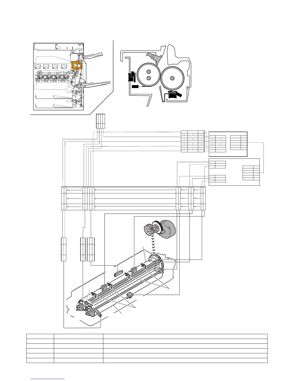
1. Electrical and mechanism relation diagram
Signal name Name Function/Operation
RTH1 Fusing temperature sensor (1) Detects the surface temperature of the fusing roller (heating). (Center section)
RTH2 Fusing temperature sensor (2) Detects the surface temperature of the fusing roller (heating). (Edge section)
HLTS1 Thermostat (1) Shuts conduction to the heater lamp when the temperature rises abnormally. [For the fusing roller (heating)]
HLTS2 Thermostat (2) Shuts conduction to the heater lamp when the temperature rises abnormally. [For the fusing roller (heating)]
HL_UM Heater lamp (1) Heats the fusing roller (heating).
CN2
CN4
INT24V1
6
D-GND
5
B03P-VL-K
HLOUT_LM
4
HLOUT_US
3
CN3
2
/HLPR
1
B6P-PH-K-S
B03P-VL-R
SM18PINRP
CN9
25
CN34
/HLPR
5
27
7
9
29
11
D-GND
3
26 D-GND
INT24V1
1
B30B-PHDSS-B
B40B-PADSS-B
DF11-4DP-SP1(PASTEL)
HLOUT_UM
2
L-HL(COM)
1
N-HL(MAIN)
1
L-HL(COM)
3
L-HL(COM)
12
TH_UM_IN
3
2
14
TH_LM_IN
15
D-GND
D-GND
D-GND
D-GND
D-GND
4
3
2
1
13
12
14
15
13
TH_US_IN
30
PCU PWB
TH_UMCS_IN
HLOUT_UM
HLOUT_US
HLOUT_LM
TH_US_IN
TH_LM_IN
N-HL(SUB)
N-HL(LOW)
HL PWB
TH_UM_IN
16
TH_UMCS_IN
16
FUM
DRAWER RWZ
1
N-HL(MAIN)
4
L-HL(COM)
3N-HL(LOW)
6L-HL(COM)
L-HL(COM)
2N-HL(SUB)
5
4
1
5
2
6
3
1TH_UM_IN9
9TH_UMCS_IN1
2D-GND8
3TH_US_IN7
4D-GND6
5TH_LM_IN
5
6D-GND4
PHNR-4-H +
BU04P-TR-P-H
PHNR-3-H +
BU03P-TR-P-H
TH_US_IN 4
D-GND 3
1
2
TH_UMCS_IN 2
D-GND
3
TH_UM_IN
1
2
1
3
PHNR-2-H +
BU02P-TR-P-H
TH_LM_IN 21
2 D-GND 1
HL_UM
HL_US
RTH3
HLTS3
HLTS1
1
2
HLTS2
RTH2
HL_LM
RTH1
2
3