MX-2300/2700 N/G PWB SECTION Q – 1
MX2700N
Service Manual
[Q] PWB SECTION
1. Disassembly and assembly
A. PWB
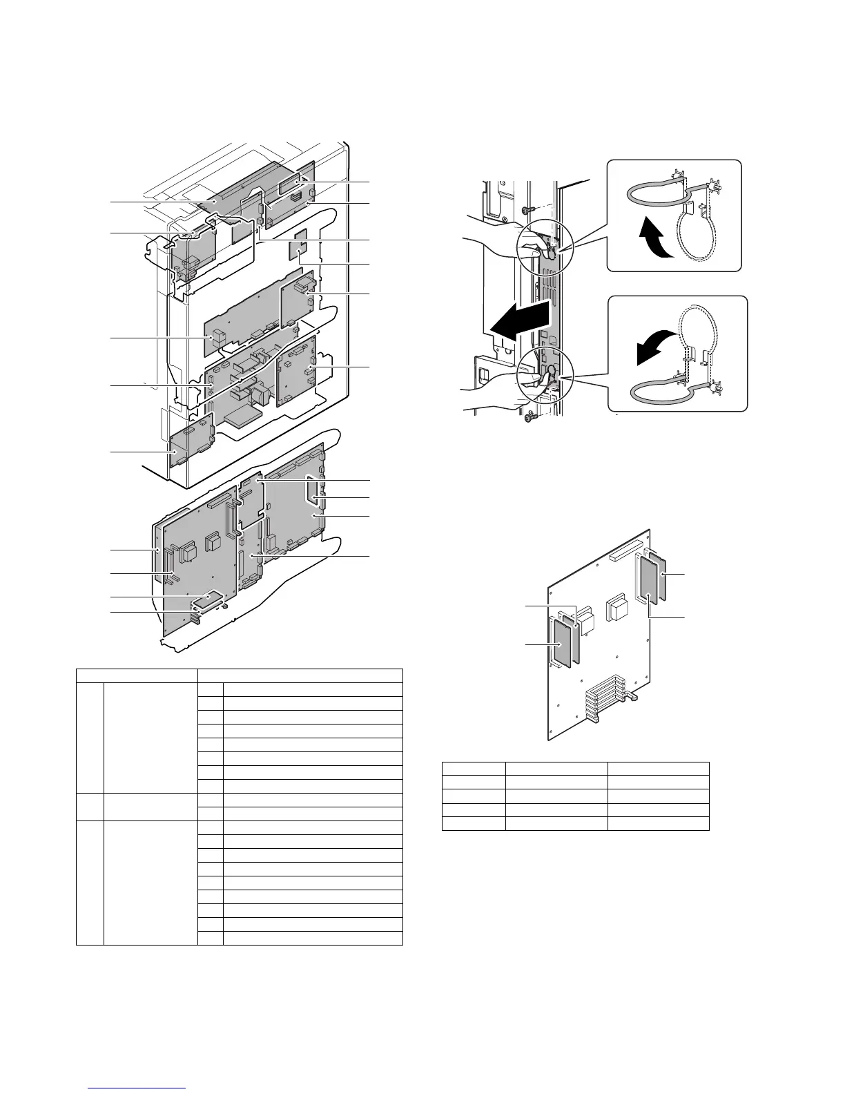
(1) Control Box
a. BOOT ROM PWB
b. PROGRAM ROM PWB
1) Remove the right rear cabinet.
2) Remove the screws and pull out the MFP cnt PWB unit.
* When placing the unit with the HDD upside, remove the
DIMM memory or insert a spacer in order to protect the
DIMM memory from pressure.
* Insertion position and insertion procedure when removing
the DIMM memory.
Unit Parts
(1) Control Box a BOOT ROM PWB
b PROGRAM ROM PWB
c MFP cht PWB
d HDD
e PCU Flash ROM PWB
f PCU PWB
g SCAN IN PWB
hMother PWB
(2) Power supply unit a AC Power PWB
b DC Power PWB
(3) Others a SCN Flash ROM PWB
b Scanner Control PWB
cHL PWB
d Driver Sub PWB
e Secondary transfer PWB
f Driver Main PWB
g Primary transfer PWB
h High Voltage MC PWB
i HVR PWB
(1)-e
(1)-b
(2)-a
(3)-a
(3)-c
(3)-g
(1)-f
(1)-h
(1)-a
(3)-d
(3)-i
(1)-c
(1)-d
(3)-b
(3)-e
(3)-f
(2)-b
(3)-h
(1)-g
MX-2300/2700 G MX-2300/2700 N
DIMM1 Option (256MB) —
DIMM2 256MB 512MB
DIMM3 512MB 512MB
DIMM4 256MB 256MB
DIMM1
DIMM3
DIMM4
DIMM2