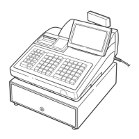
7
AC power cord
➀
Connect the AC power cord to the AC adapter.
➁
Open the plug frame and connect the AC adapter
plug to the AC adapter jack.
➂
Close the plug frame and lock the AC adapter plug
to prevent disconnection.
➃
Plug the AC power cord into the wall outlet.
➀
➁
➃
➁
➂
AC adapter
AC power cord
AC adapter plug
AC adapter jack
Plug frame
Mode switch
Side cover
Bottom cabinet
Contactless clerk switch
Power indicator
Operator display (touch panel)
1
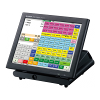
Part Names and Functions
This chapter describes the part names and functions of this POS terminal.
External View
■■
■■
■ Front view
■■
■■
■ Rear view
Mode switch
The switch has the position ON ( I ) and STANDBY ( ).
Set the mode switch to the ON ( I ) position after the terminal has been plugged into the wall outlet.
The STANDBY (
) position locks all operations of the POS terminal. When you select this position, the
screen will disappear.
Power indicator
When the mode switch is set to the ON ( I ) position with the POS terminal plugged in, the power indicator
at the lower right corner of the LCD panel will light up. When the mode switch is set to the STANDBY (
)
position or the POS terminal is unplugged, the power indicator will light out. The power indicator will remain
on while the display’s backlight is off.