6.4 Preparations for Adjustment
(1) Remove the two screws on the rear for fixing the instrument cover, remove the filter cover on
the right panel and the filter side, and remove the instrument cover.
(2) Loosen the knurled screw (white) on lamp cover 1, and remove lamp cover 1 and the filter.
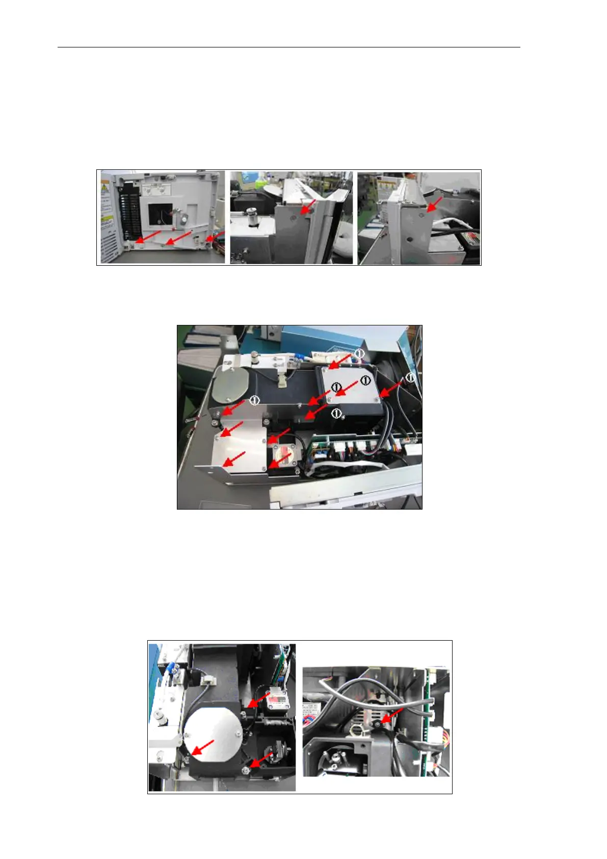
(3) Remove the front panel assembly. Remove the five screws (indicated by arrows) for fixing the
front panel, and remove and place the front panel assembly to the side of the instrument with
the cable for RF-20 KEY, cable for leak sensor, and cable for lamp cover sensor still
connected to the CPU board.
(4) Loosen the ten screws (indicated by arrows), and remove the excitation monochromator and
emission monochromator covers. Screws marked by (1) (indicated by arrows) are provided
with washers for preventing screws from falling.
(5) Removing the emission monochromator
Loosen the cable clamps fastening the Xenon power supply cable, minus (black); cable, EM
motor; and cable, EMHP shown in the photo below, and disconnect the cables.
Remove the three M512 bolts (indicated by arrows) with an hexagonal wrench (4 mm) and
the M43 screw in the photo on the right with a Phillips screwdriver, disconnect the cable, EM
motor (J11) and cable, EMHP (JI12), and lift up the emission monochromator to the height of
the positioning pin to remove.
(6) After removing the emission monochromator, place it on its side.