6.8 Fine-Adjustment of the Light Source Mirror (Oval Surface Mirror)
(1) With the EX grating at the 0-order light position, enter "500" at "EX PULSE" to select the light
at about 350 nm.
(2) Remove the cell position target jig from the cell position.
(3) Remove the light-filtering jig.
Note: When removing the light-filtering jig, be sure to adopt burn preventative measures
such as wearing gloves, since the jig is heated by the lamp.
(4) In the case of the XS, turn the TORX screw to the left or the right to remove the reflected light
of the back mirror away from the slit since the reflected light from the back mirror obstructs
fine-adjustment of the light source mirror.
(5) Display the light energy monitor value of the reference side.
(Display "ENTER" and "SMPL EN/REF EN" at "MONITOR".)
(6) Fine-adjust the light source mirror by the procedure in step (3) of "6.5 Rough-Adjustment of
the Light Source Mirror (Oval Surface Mirror)" so that the value of "REF EN" exceeds "180".
(On new instruments, the value "180" of "REF EN" is taken as the reference since the lamp
causes fluctuations in the light intensity.)
(7) In the case of the XS, visually approximately position the back mirror also, and then adjust
the back mirror so that the value of "REF EN" becomes its maximum value. (Adjust the three
screws in the same way as for light source mirror adjustment, except that in this case, the
screws are TORX screws.)
(8) In the case of the XS, visually approximately position the back mirror also, and adjust the
back mirror so that "REF EN" becomes its maximum value. (Adjust the three screws in the
same way as for light source mirror adjustment, except that in this case, the screws are
TORX screws.)
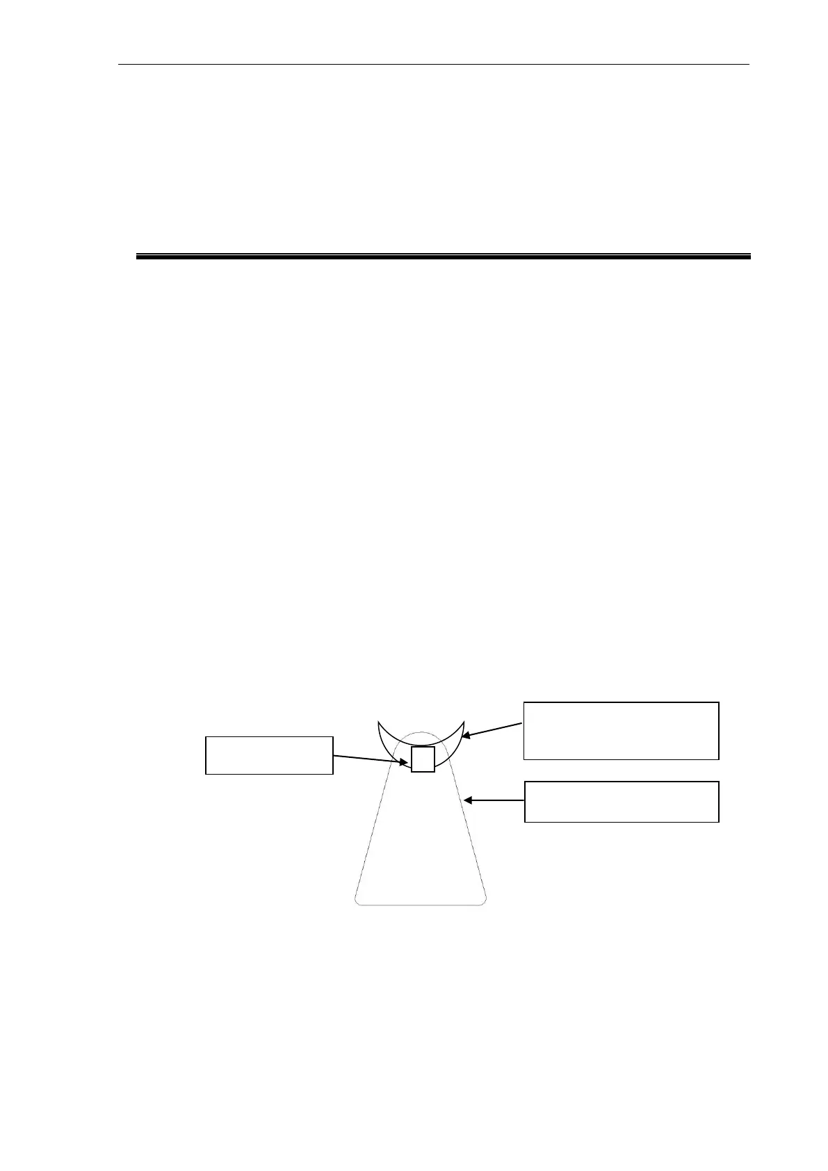
(The Xenon light emission point image on the back mirror is V-shaped like that shown in the
figure below. Adjust so that the area near its tip is aligned with the slit opening.)
Xenon light emission point
image
Back mirror
Xenon light emission point
image