6.6 Adjusting the Excitation Grating
(1) Remove the EX grating.
(2) Enter "0" at "FACTORY" - "EX PULSE". (The home position is detected again if "0" is entered
even with "0" already entered at "EX PULSE".)
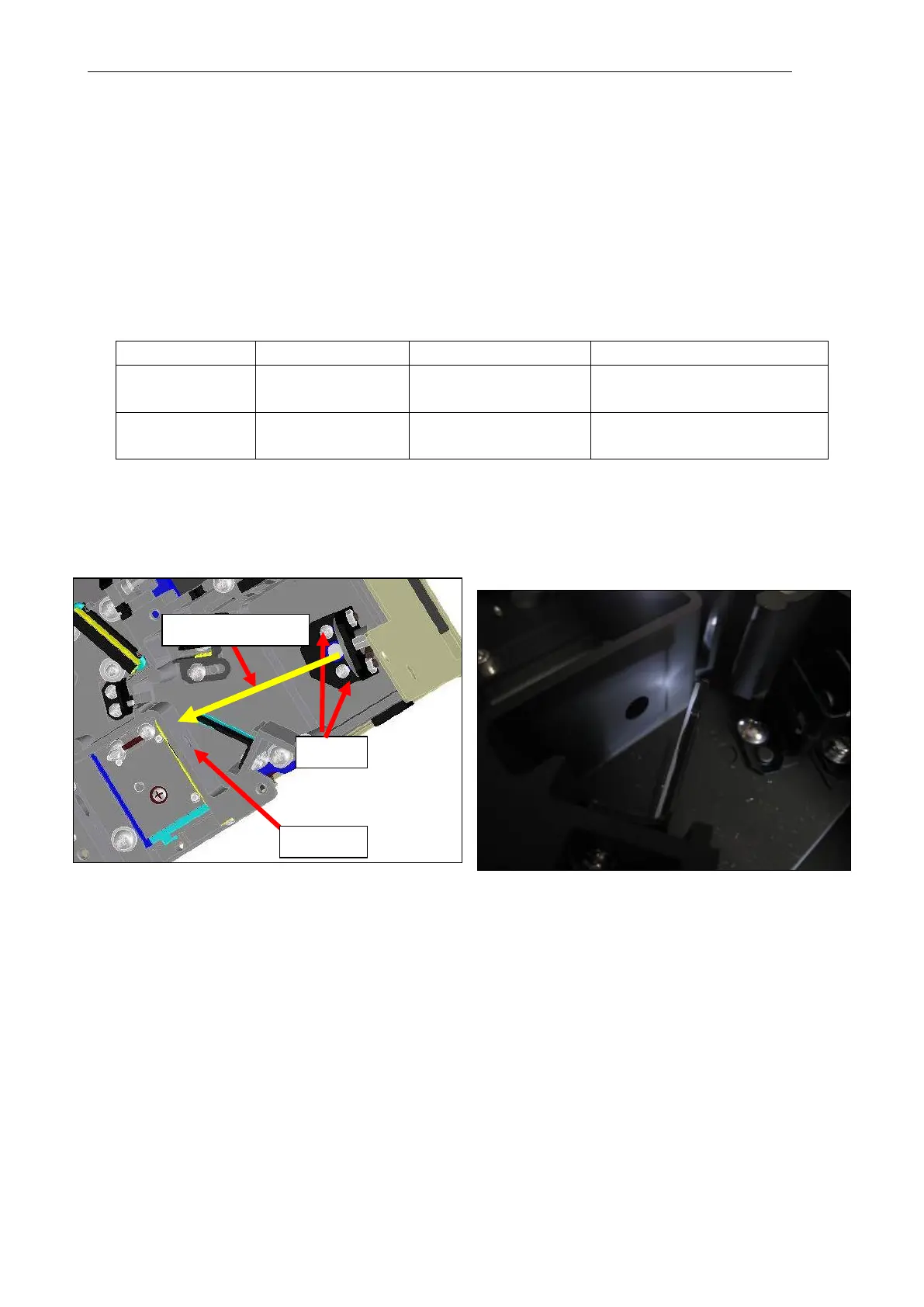
Adjust the screw so that the 0-order reflected light at the location indicated in the figure is
almost aligned with the beam splitter end surface (slit side).
(Check by the shadow projected on the wall.)
[Reference: Relationship between pulse and wavelength]
EX(EM) PULSE = 0.7 nm/pulse
The table below summarizes PULSE indicated values and approximate wavelengths.
Approx. 630 nm (red light)
The EX grating moves by the pulses equivalent to the plus/minus value entered at "EX
PULSE", and the display indicates the total incremented/decremented value equivalent to
the plus/minus value entered.
(3) Mount the EX grating on the holder and fasten temporarily.
Reference: Mount the EX grating with the serial No. facing up and the recess (notch) facing
down.