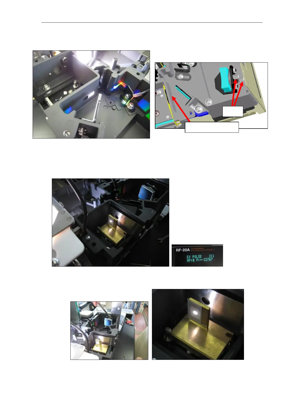
(4) Tighten or loosen the two screws in the figure below with a 5.5 mm spanner, adjust the tilt of
the grating, and approximately align the height of the 0-order light flux with the center of the
7 mm dia. opening in the figure.
(5) Mount the cell position target jig (P/N228-52369-91) at the cell position.
(6) Enter "200" (0-order light) at "EX PULSE", bring the 0-order light to the cell position target jig,
fine-adjust by further entering "1" or "-1" at "EX PULSE", and align the 0-order light with the
cross mark position of the cell position target jig.
Reference: On this instrument, the "EX PULSE" value was "211" when the 0-order light was
aligned with the cross mark position.
(7) Repeat step (3) again, and align the 0-order light flux with the crossmark position of the cell
position target jig in the vertical direction. (Dead center is best, however, slightly below this
position also is acceptable.)