(4) Adjust the "-HV SENS2 xxx" voltage value according to the "-HV SENS2 xxx" value in
the FACTORY mode, so that signal value on the WS matches the F value recorded before
replacing the photomultiplier (50, for example).
15.6.3 Adjusting [Sens1]
(1) Set [GAIN] to 1 (x1) and [SENS] to 1 (high).
(2) Set [EX] to 350 nm and [EM] to 450 nm, then adjust the zero position.
(3) Adjust the EM wavelength(397nm, for example) to the peak value of the Raman
spectrum of water and output the F value on the WS.
(4) Adjust the "-HV SENS1 xxx" value according to the "-HV SENS1 xxx" value in the
FACTORY mode, so that signal value on the WS is 400, 8 times the F value (50).
15.6.4 Adjusting [Sens3]
(1) Set [GAIN] to 3 (x16) and [SENS] to 3 (low).
(2) Set [EX] to 350 nm and [EM] to 450 nm, then adjust the zero position.
(3) Adjust the EM wavelength(397nm, for example) to the peak value of the Raman
spectrum of water and output the F value on the WS.
(4) Adjust the "-HV SENS3 xxx" value according to the "-HV SENS3 xxx" value in the
FACTORY mode, so that signal value on the WS is 6.25, 1/8 of the F value (50).
(5) [Z WAVE] is changed into 0 and carried out as before.
Chapter 16 is an additional page.
16 Base ASSY, XS (including Peltier Unit)
Replacement Procedure
16.1 Checkpoint of a Base ASSY,XS
The Base ASSY, XS (P/N: 228-45892-91) and the Peltier ASSY (P/N: 228-51008-41) is a set
unit. The Peltier ASSY cannot be purchased as a single piece of a maintenance part.
Accordingly, regardless of the Peltier ASSY replacement, the both ASSYs have to be replaced
together.
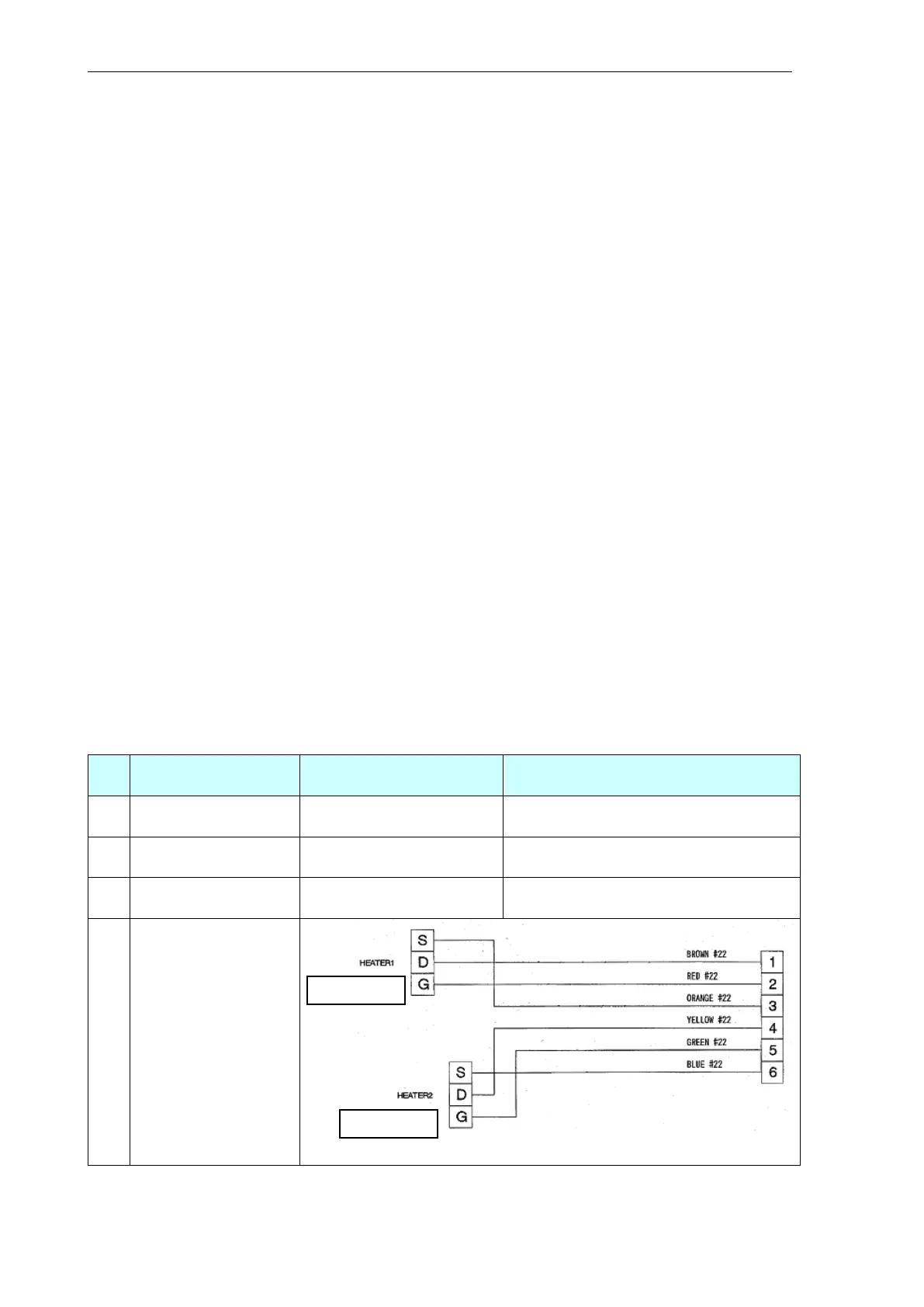
About 12.5 kΩ(20 degC)、10.2 kΩ(25
degC)、8.3 kΩ(30 degC)
Overheat breaker
(thermostat)
Circuit Diagram of
Heater ASSY