EasyManuals Logo

Shimadzu RF-20A User Manual

Shimadzu RF-20A
91 pages
To Next Page IconTo Next Page
To Previous Page IconTo Previous Page
Page #25 background imageLoading...
Page #25 background image
25
6.7 Adjusting the Photodiode Assembly (PD ASSY) and Beam Splitter
(1) Following on from section 6.5 (10), make sure that the 0-order light is at the center of the cell
position target jig.
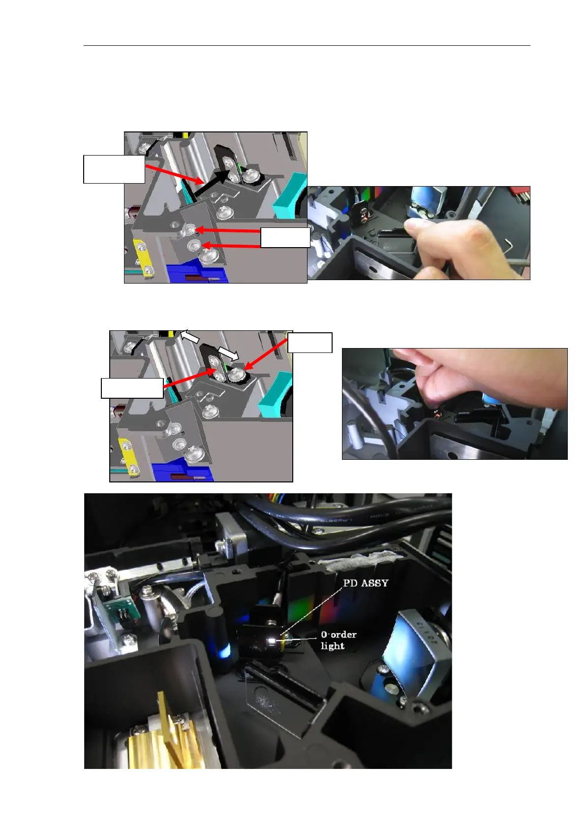
(2) Loosen the two screws in the figure below, adjust the tilt of the splitter so that the height of
the reflected light flux (0-order light) is the same as the height of the slit on the PD ASSY.
(3) Loosen the screw in the figure below, and adjust the left/right position of the PD ASSY so that
the slit is aligned with the center of the reflected light (0-order light).
Screws
Reflected
light flux
Screw
Slit

Table of Contents

Questions and Answers:

Question and Answer IconNeed help?

Do you have a question about the Shimadzu RF-20A and is the answer not in the manual?

Shimadzu RF-20A Specifications

General IconGeneral
BrandShimadzu
ModelRF-20A
CategorySecurity Sensors
LanguageEnglish

Related product manuals