10 FACTORY Parameters
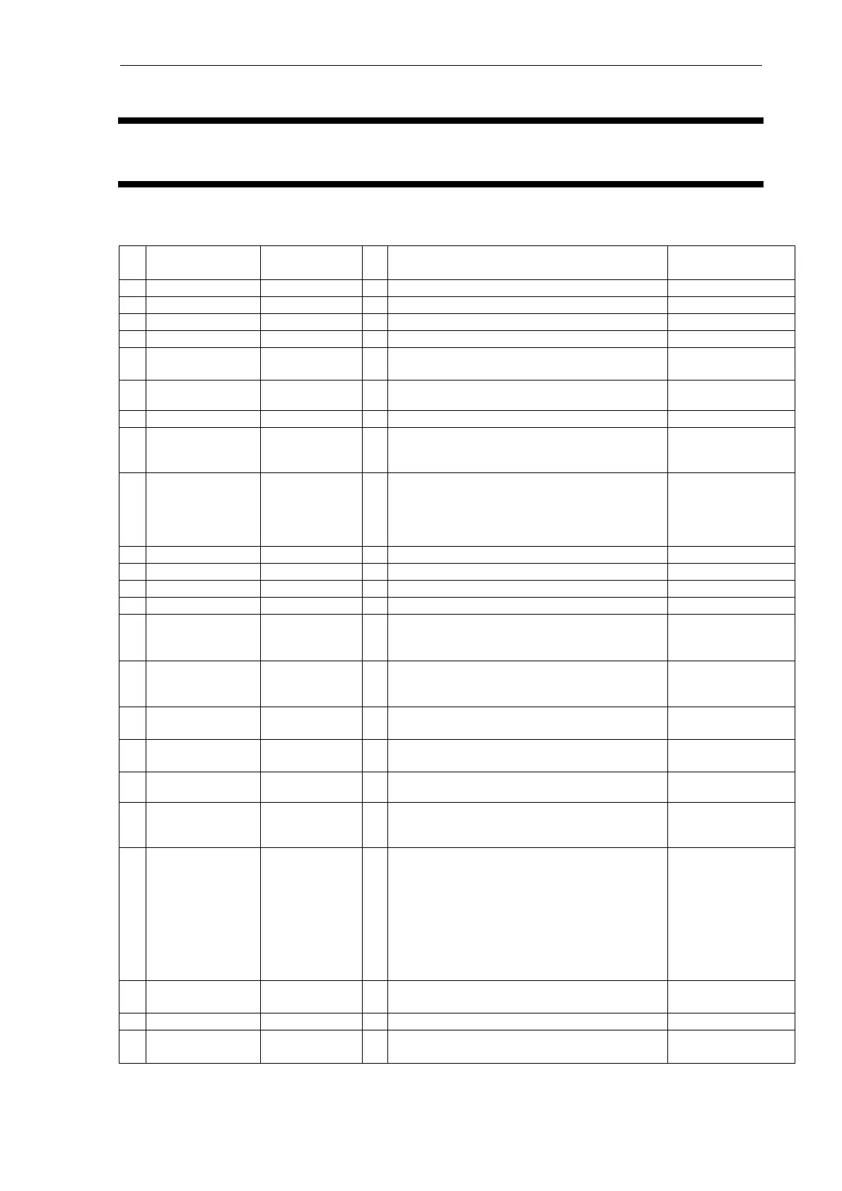
10.1 FACTORY parameter list
As for the parameter to which F was attached, only FACTORY mode is displayed.
Single-wavelength/Dual-wavelength selection
screen
Lamp lighting setting screen
Sensitivity setting screen
0: No filter, 1: 0.05, 2: 0.1, 3: 0.5, 4: 1.0, 5: 1.5,
6:3.0, 7:6.0, 8:8.0, 9:10.0, 10:2.0
Sensitivity calibration start screen
See 8.2
Compensating and
Verifying Sensitivity
at the Factory
(Reference)
Sensitivity 1 (HI) direct input screen
Sensitivity 2 (MID) direct input screen
Sensitivity 3 (LOW) direct input screen
Analog 1 output mode setting
8: Cell temperature, 9: Room temperature
output (0C =0 mV to 100C =10 mV)
Analog 2 output mode setting
8: Cell temperature, 9: Room temperature
output (0C=0 mV to 100C =10 mV)
0: Auto zero ON/1: Auto zero OFF (Other
settings are ignored.)
0=S only output, 1=S/R both output (default),
2=R only output
S: Sample side, R: Reference side
Performs wavelength calibration. In the case of
the 20A, the Mercury lamp jig is required. After
calibration, the wavelength check is performed.
The wavelength calibration/check are performed
continuously at the
EX254 nm/EX507 nm/EX761 nm/
EM254 nm/EM507 nm/EM761 nm settings, and
finally the resulting wavelength variance is
displayed.
Monitor: Reference energy