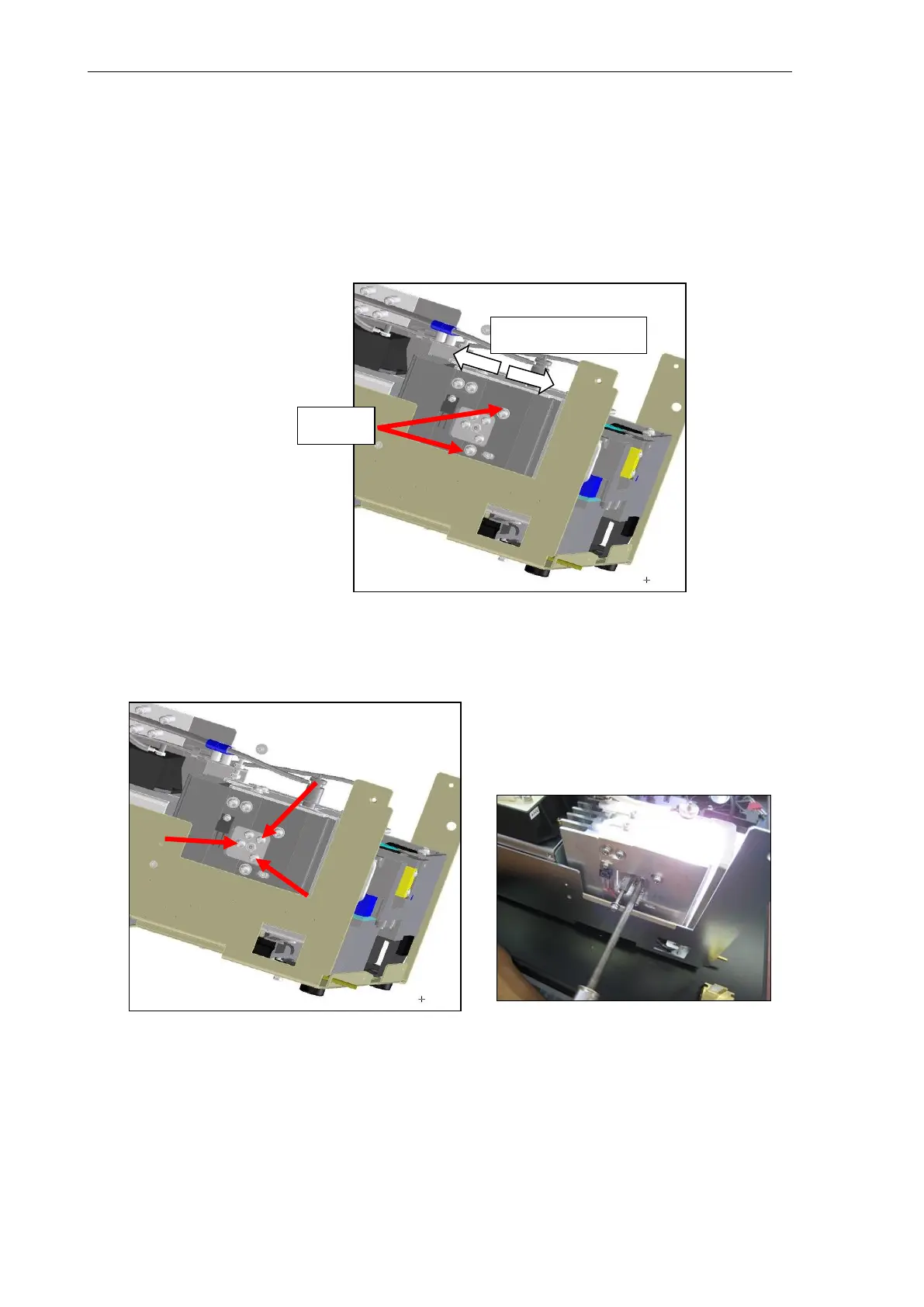
(2) Loosen the two screws indicated in the figure, and adjust the forward/backward position of
the light source mirror so that the image of the light emission point becomes long and thin in
the vertical direction symmetrically on the left and right. (Any light emission point position is
acceptable.)
The mirror moves smoothly with the lower screw being held down with the screwdriver,
and the mirror moved forward/backward while pulling the spacer towards the front. (Note
that the mirror will move when the screw is tightened if it is loosened excessively.)
In the case of the XS, remove the optical axis of the back mirror from the excitation inlet
slit using TORX screwdriver T10 since it obstructs adjustment of the light source mirror.
(3) Tighten or loosen each of the three screws in the figure below to focus the image of the light
emission point at the excitation inlet slit.
Backward/forward
direction
 Loading...