PIN Signal Wire color
1
Function
4 - Black Do not use
1
When using pre-assembled cables.
NOTE
Pin 2 and 4 must not be connected; this can lead to destruction of the absolute
encoder.
Table 29: Pin assignment of the Ethernet port 1 and 2 connections
PIN Signal Wire color
1
Function
1 TxD+ White/orange Ethernet
2 RxD+ White/gray Ethernet
3 TxD- Orange Ethernet
4 RxD- Green Ethernet
1
When using pre-assembled cables.
NOTE
b
Connect the screen to the encoder housing.
b
Observe the maximum lengths of cable.
b
Mount all cables with strain relief.
4.2 Settings on the hardware
The following elements for adjustment are located under the screw cover:
•
Three address switches
•
Preset pushbutton
b
Open the screw cover using a screwdriver for slotted screws with a blade width of
min. 10.0 mm.
4.2.1 IP address setting
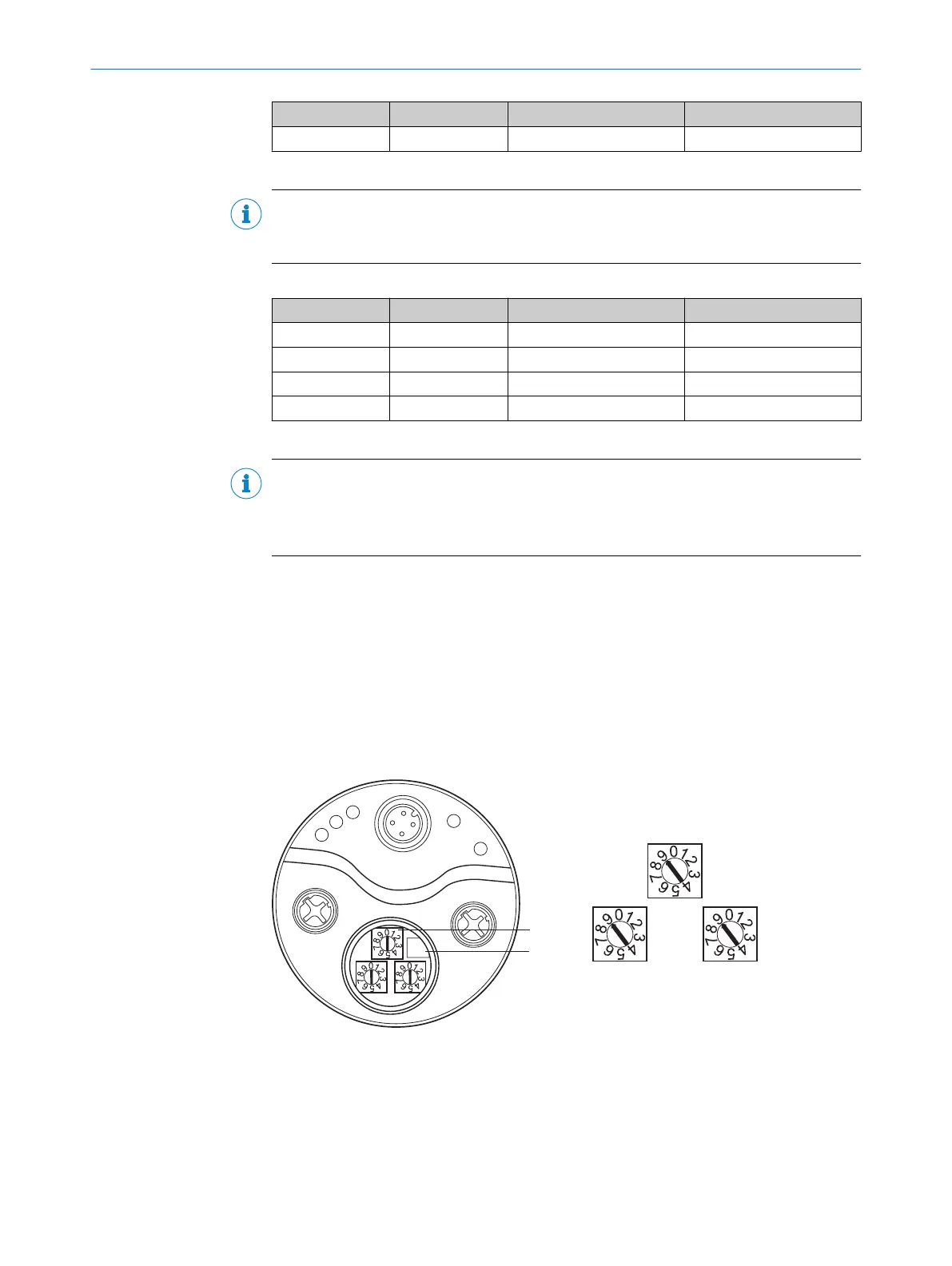
Figure 19: Address switch and preset pushbutton
1
Address switch
2
Preset pushbutton
3
Hundreds place
4
Tens place
5
Ones place
4 COMMISSIONING
44
O P E R A T I N G I N S T R U C T I O N S | AFS/AFM60 EtherNet/IP 8014213/1EF3/2021-12-08 | SICK
Subject to change without notice

 Loading...


