Figure 60: Loading configuration
✓
The status indicators for Run Mode, Controller OK and I/O OK turn green.
Figure 61: Communication status
5.7.3 Checking communication
The data received by the controller from the encoder can be displayed in order to check
that communication between the controller and the encoder is working correctly.
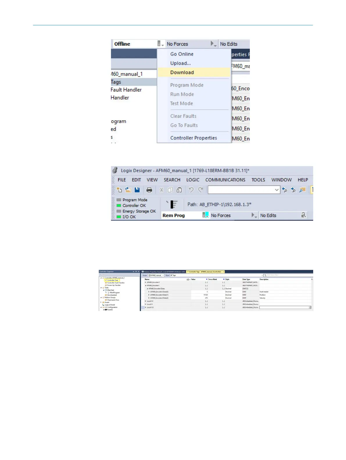
Figure 62: Checking communication
1. In Controller Organizer, open the Controller AFM60_manual_1 → Controller Tags folder.
2. Under Name, open the AFM60_Encoder:I → AFM60_Encoder:I.Data item in the Controller
Tags column.
Displayed data in the example:
•
AFM60_Encoder:I.Data[0]: Fault header: 0
•
AFM60_Encoder:I.Data[1]: Position: 15130
•
AFM60_Encoder:I.Data[2]: Speed: 270 turns/min
5.8 Programming examples
The following examples show the configurations of two programs that read (tempera‐
ture) or write (preset) acyclic data. For this purpose, the programs are written in the
form of ladder logic using the RSLogix 5000 software from Rockwell Automation.
CONFIGURATION USING A PLC 5
8014213/1EF3/2021-12-08 | SICK O P E R A T I N G I N S T R U C T I O N S | AFS/AFM60 EtherNet/IP
71
Subject to change without notice

 Loading...


