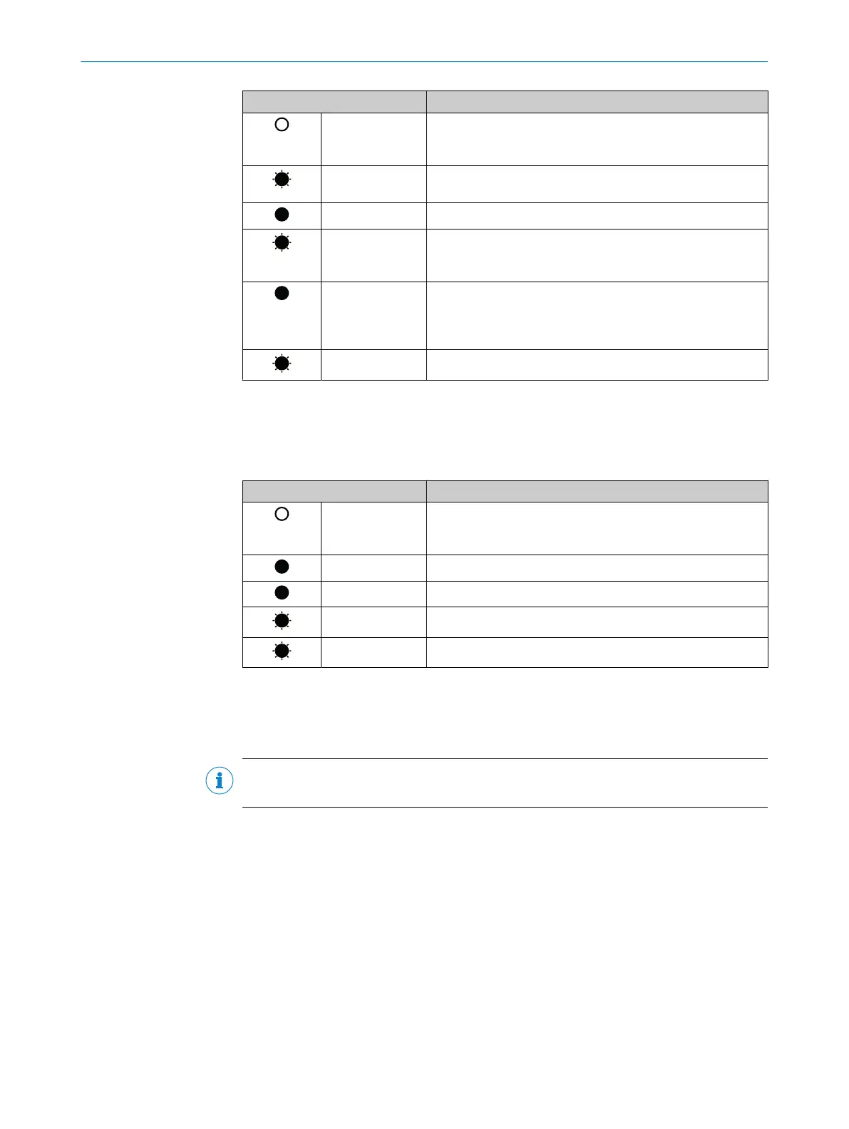
Display Description
Off No supply voltage
or
No IP address
Green Warning
Incorrect parameter
Green Device in operation
Red Warning, but device still ready for operation
or
Firmware update in progress
Red Error
Encoder error
or
Restart after firmware update in progress
Red/green Self-test when switching on
Link 1 and 2 Ethernet link LEDs
The Link 1 and 2 Ethernet link LEDs indicate the physical connection status of the
Ethernet interface.
Table 32: Meaning of the Link 1 and 2 LEDs
Display Description
Off No supply voltage
or
No Ethernet connection
Green Ethernet connection established
Yellow Interface port locked
Green Data transmission TxD/RxD
Yellow Data collisions
7.3.2 Self test via EtherNet/IP
A self-test is available to check the sensor system and the most important functions of
the encoder.
NOTE
The self-test may only be performed when the encoder is at standstill.
The self-test can be triggered via the diagnostic bit of attribute ID 0Dh in the position
sensor object (see table 24, page 29). If an error occurs, bit 27 of the Fault header is
set (see table 33, page 108).
Following the self-test, the diagnostic bit of attribute 13 is automatically reset to 0.
7.3.3 Warnings, alarms and errors via EtherNet/IP
Within EtherNet/IP, warnings, alarms and errors can be retrieved via implicit messages
as well as via explicit messages.
If connections are established via the I/O assembly, the Fault header can be read out
via instances 101, 102 and 103 as well as instances 101WS, 102WS and 103WS (see
table 18, page 23).
TROUBLESHOOTING 7
8014213/1EF3/2021-12-08 | SICK O P E R A T I N G I N S T R U C T I O N S | AFS/AFM60 EtherNet/IP
107
Subject to change without notice

 Loading...


