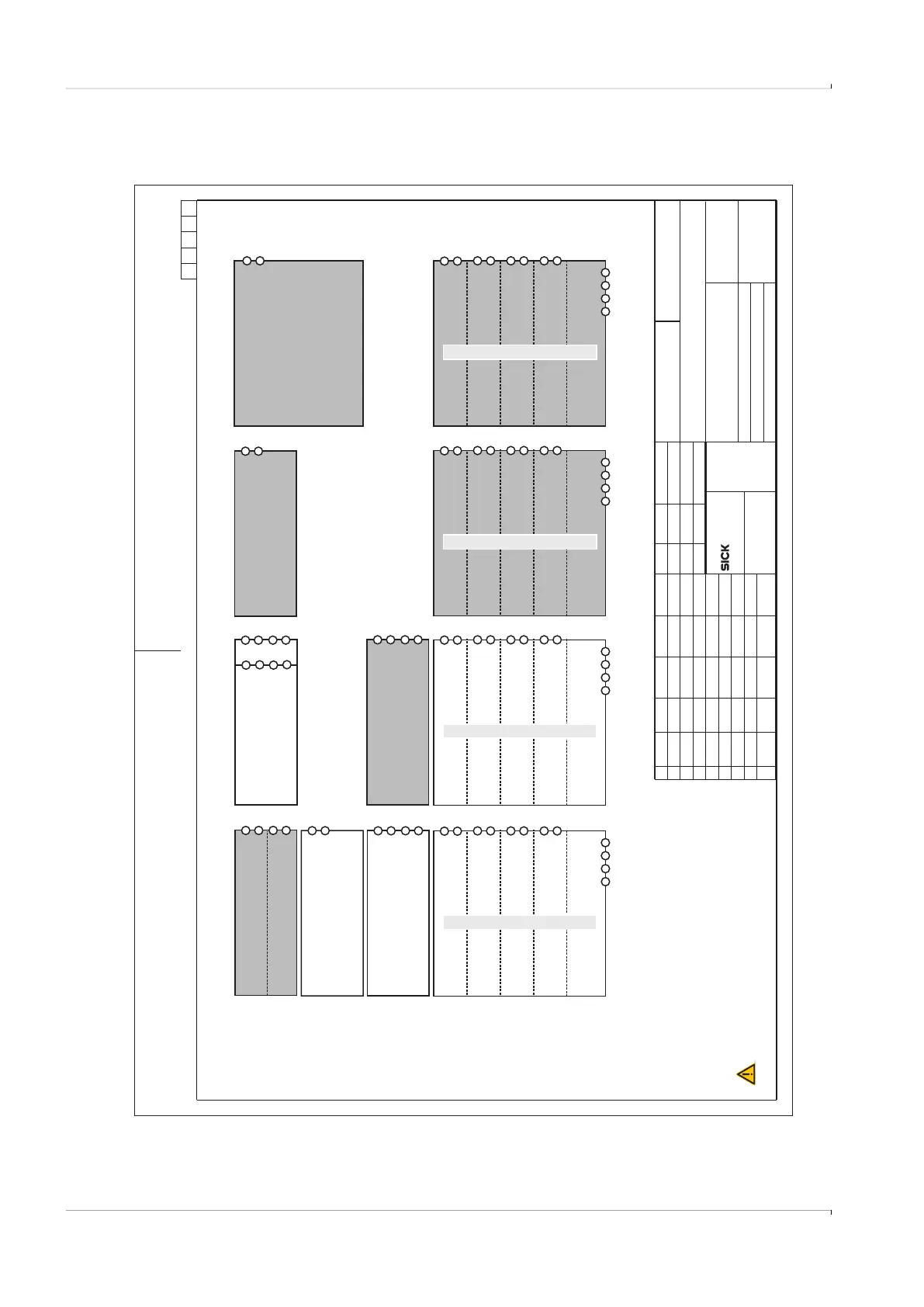
Fig. 79 Connection diagram 9236581 (page 14)
Vervielfaeltigung dieser Unterlage sowie Verwertung und Mitteilung ihres
Inhaltes unzulaessig, soweit nicht ausdruecklich zugestanden. Zuwiderhand-
lungen sind strafbar und verpflichten zu Schadenersatz (LitUrhG, UWG, BGB).
Alle Rechte fuer den Fall der Patenterteilung oder GM-Eintragung vorbehalten.
A4_Formblatt_ME10.CDR
SICK Engineering GmbH
Bergener Ring 27
01458 Ottendorf-Okrilla
Verteildatum:
Page
Norm-Typ/DIN
Ersatz für:
Änderung
gepr.
gez.
Tag Name
Ind. Tag Name
Maßstab:
Werkstoff
Ersetzt durch:
Gepr.
Ursprung:
14 of 15
9236581
Ui=20V
Pi = 717 mW
Ui=20V
Pi = 717 mW
Ui=20V
Pi = 717 mW
Ui=20V
Pi = 717 mW
+-
+-+-+-
DO.3
optical isolated
DO.2
optical isolated
FO.1
optical isolated
FO.0
optical isolated
DO-LF
Ui = 10.5 V
Pi = 717 mW
Ci = 1.21 μF
Li = 0.02 mH
RS485
optical isolated
needs ext. power
AB+-
Ui = 10.5 V
Ci = 1.21 μF
Pi=1W
Li = 0.02 mH
RS485, potted
optical isolated
needs ext. power
AB+-
Uo = 8.2 V
Io = 384 mA
Po = 692 mW
Co = 6.4 μF
Lo = 0.2 mH
AB+-
Ui = 26.6 V
Ii = 667 mA
Pi=1W
Ci = 1.2 nF
Li = 0.01 mH
AO
optical isolated
potted
+-
Ui=30V
Pi=1W
Ui=30V
Pi=1W
Ui=30V
Pi=1W
Ui=30V
Pi=1W
+-
+-+-+-
DO.3
optical isolated
DO.2
optical isolated
FO.1
optical isolated
FO.0
optical isolated
DO-HF, potted
Ui = 26.6 V
Ii = 667 mA
Pi=1W
Ci = 1.2 nF
Li = 0.01 mH
AO + HART
optical isolated
potted
+-
Ui = 18.2
Pi=1W
ENCODER
optical isolated
+-
Ui=30V
Pi = 717 mW
Ui=30V
Pi = 717 mW
Ui=30V
Pi = 717 mW
Ui=30V
Pi = 717 mW
+-
+-+-+-
DO.3
optical isolated
DO.2
optical isolated
FO.1
optical isolated
FO.0
optical isolated
DO-HF
Ui=20V
Pi=1W
Ui=20V
Pi=1W
Ui=20V
Pi=1W
Ui=20V
Pi=1W
+-
+-+-+-
DO.3
optical isolated
DO.2
optical isolated
FO.1
optical isolated
FO.0
optical isolated
DO-LF, potted
PT-SENSOR
non- isolated
RS485
Ui=17.7Vor
Ui = 26.6 V Pi=1W
Ci = 1.2 nF
and
Uo = Uin, Io = Uin / 267 Ohm
Po = 1/4 Uin / 267 Ohm
Co=92nF
2
+- +-
POWER SENSOR
HART-PT
non-isolated
potted
ext. Power
6...16 Vdc
-+-+
Ui = 26.6 V
Ii = 667 mA
Pi=1W
Ci = 1.2 nF
Uin
WARNING:
AVERTISSEMENT:
EXPLOSION HAZARD
Substitution of components may impair Intrinsic safety
RISQUE D` EXPLOSION - La substitution
de composants peut compromettre la securite intrinseque.
-40°C < Tamb < 70°C
Read operation instructions before installation.
For alternate module types increased safety parameters may be
considered as shown in bold letters.
Alternate potted module types have to be marked with “Pi=1W”
on the top side of the PCB additionally.
kochami
kochami
2015-10-30
Control Drawing FLOWSIC600-XT CSA
2016-01-27
Class I Division 1, Groups A, B, C, D, T4
Ex ia Intrinsically Safe; Securite Intrinseque
Ex ia IIC T4 Ga
Class I Zone 1 AEx ia op is IIC T4 Ga
FLOWSIC600-XT Ex ia module types, see page 1...12 for using. Terminals: Wire size 0.25...1.5 mm 24...16 AWG,
2
, resp. Tightening torque 0.22...0.25 Nm
Ui=20V
Ii = 667 mA
Pi = 1.65 W
Li = 0.005 mH
Ui=20V
Ii = 667 mA
Pi = 1.65 W
Li = 0.005 mH
Ui=20V
Ii = 667 mA
Pi = 1.65 W
Li = 0.005 mH
Ui=20V
Ii = 667 mA
Pi = 1.65 W
Li = 0.005 mH
ext. Power
6...16 Vdc
-+-+
ext. Power
6...16 Vdc
-+-+
ext. Power
6...16 Vdc
-+-+
01
ZAK3
kochami
kochami
2017-03-29
2017-03-29