54 FLOWSIC600-XT · Operating Instructions · 8018846/1BHP/V2-1/2021-05 · © SICK Engineering GmbH
Installation
Subject to change without notice
3.3.4.2 Fitting the FLOWSIC600-XT in the pipeline
1 Use the lifting gear to position the FLOWSIC600-XT in the desired location in the pipe-
line.
2 Lead the pipelines free of tension to the device being fitted.
3 Check for correct seating and alignment of the flange gaskets after installing the flange
bolts, but prior to tightening. The gaskets must not project into the area through which
the gas flows.
4 Align the FLOWSIC600-XT so that the offset of the inner diameters (bore) between inlet
section, meter body and outlet section is as small as possible.
5 Insert the remaining fastening bolts and tighten the nuts cross-wise. The tightening
torque applied must not be lower than specified in the project planning.
6 Fit the pressure sensing line between the pressure tap and pressure transmitter.
7 Slowly increase the pressure in the pipeline.
8 Carry out a leak tightness check on the pipeline (in accordance with the pipeline
manufacturer's specifications). In case of a water pressure test in the installation, see
Section 3.2.3 “Hydrostatic test in the installation” for further information.
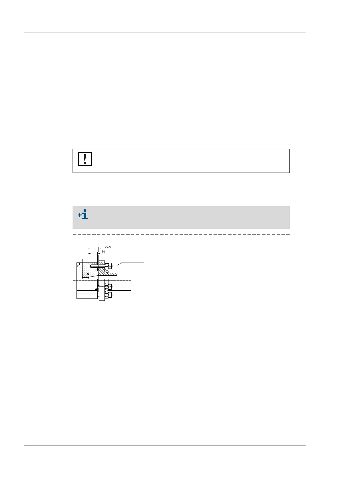
Fig. 25 Borehole diagram
The threaded bolt is to be screwed through the washer of the connection pipe into the blind
hole thread of the meter body and fixed with a lock nut. Observe the maximum screw-in
depth. (see Table “Mounting sets”)
NOTICE: Observe allowed pressure change
The pressure change within the measuring section must not exceed
0.5 MPa/min in order to protect ultrasonic transducers and seals.
The FLOWSIC600-XT meter body in the nominal widths DN80/3" or DN100/4"
(interchangeable) is flangeless with a blind hole thread. The hole pattern corre-
sponds to the DIN or ANSI standard, depending on the design.
Cross Section